Internal liquid suction heat exchanger

a heat exchanger and liquid suction technology, which is applied in indirect heat exchangers, lighting and heating apparatuses, refrigeration components, etc., can solve the problems of excessive oil circulation, low discharge superheat, and oil may not be effectively separated from the discharge gas in the oil separator

Inactive Publication Date: 2017-08-31
CARRIER CORP
View PDF6 Cites 5 Cited by
  • Summary
  • Abstract
  • Description
  • Claims
  • Application Information

AI Technical Summary

Problems solved by technology

With the adoption of low global warming potential (GWP) refrigerants, the characteristics of refrigerant cycles may result in lower discharge superheat.
Due to the lower discharge superheat, oil may not be effectively separated from the discharge gas in the oil separator.
This may cause excessive oil circulation, oil foaming in the evaporator, and / or a loss in performance.
Further, a refrigerant may contain residual atomized liquid particles (carryover) at the end of a heat exchange stage (mostly due to low superheating of the vapor and high vapor exit velocities), which may damage components downstream of the heat exchanger or result in operational issues.
In addition, some known systems have poor versatility in response to changes in the fluid temperature and flowrate requirements downstream.

Method used


Image

  • Internal liquid suction heat exchanger
  • Internal liquid suction heat exchanger
  • Internal liquid suction heat exchanger

Examples


Embodiment Construction

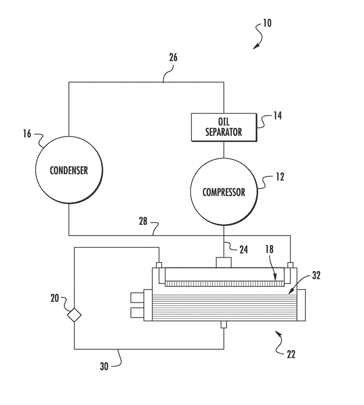
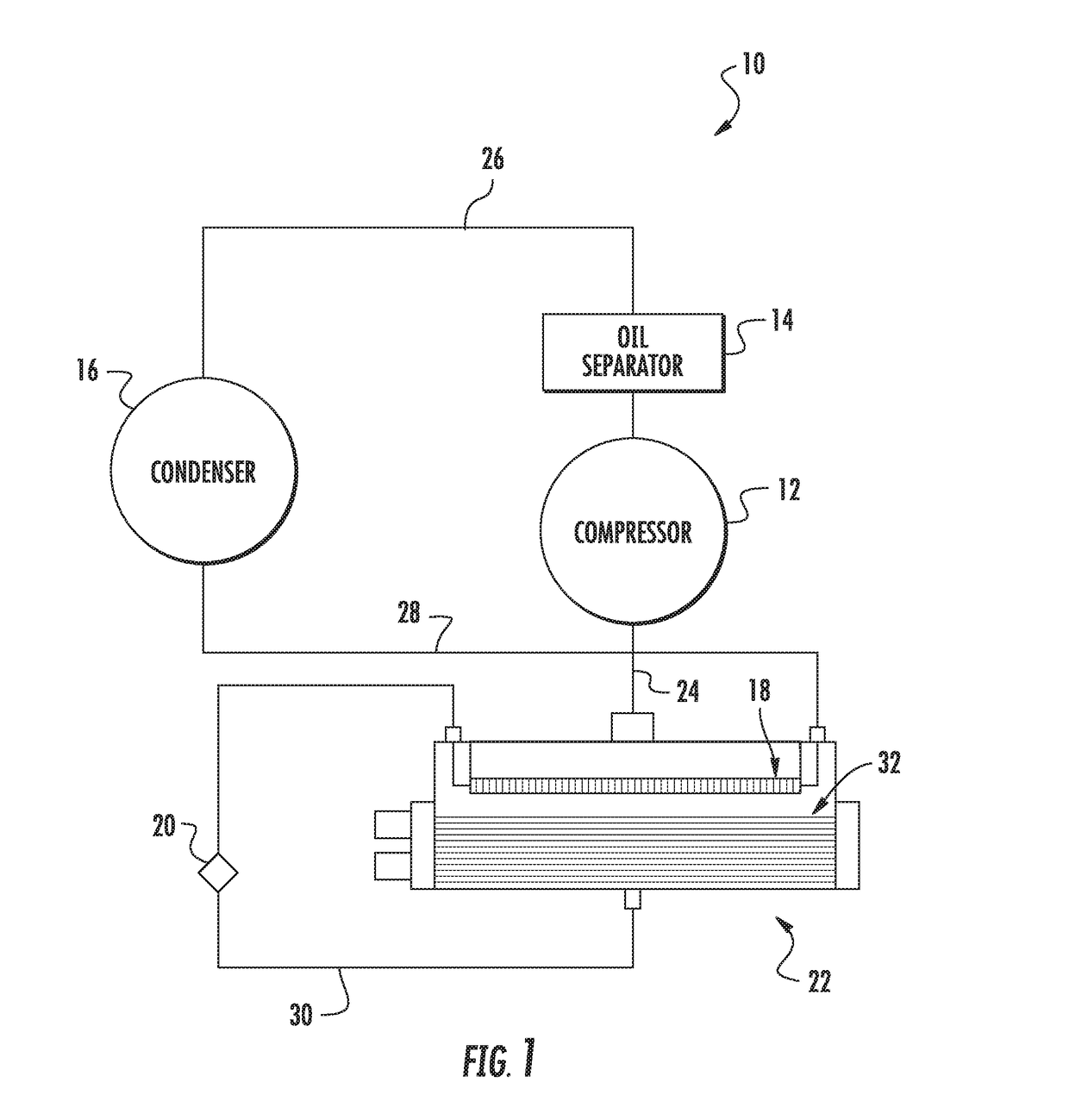
[0012]Described herein is an evaporator or chiller that includes a liquid suction heat exchanger installed inside the evaporator. The liquid suction heat exchanger increases suction superheat, by transferring heat form the liquid refrigerant leaving the condenser to the refrigerant gas existing in the evaporator heat exchanger, thereby increasing system efficiency and capacity. Transferring heat from the refrigerant gas leaving the evaporator to the liquid refrigerant is a cycle enhancement that is used to improve the performance of a refrigeration system as well as add additional superheat to the suction gas to enable better control of refrigerant flow control devices (e.g., expansion valves).

[0013]FIG. 1 illustrates an exemplary refrigeration system 10 that generally includes a compressor 12, an oil separator 14, a condenser 16, a liquid suction heat exchanger 18, an expansion valve 20, and an evaporator 22. In the exemplary embodiment, compressor 12 is a screw compressor and evap...


PUM


Abstract

In one aspect, an evaporator assembly for a refrigeration system is provided. The evaporator assembly includes a pressure vessel having an inlet and an outlet. The outlet is configured to supply refrigerant to a compressor of the refrigeration system. A liquid suction heat exchanger is disposed within the pressure vessel. The liquid suction heat exchanger is configured to receive a liquid refrigerant for heat exchange with the refrigerant in the pressure vessel.

Description

FIELD OF THE INVENTION[0001]The subject matter disclosed herein relates to heat exchangers and, more specifically, to flooded evaporator heat exchangers for use in refrigeration systems.BACKGROUND[0002]Compressors are commonly employed to circulate a refrigerant through a refrigeration cycle in a cooling system. One particular use of the compressor is in a refrigeration system commonly known as a chiller. In addition to the compressor, the typical chiller also includes a condenser, an evaporator or cooler, and in some applications an oil-refrigerant separator. These components are connected to each other by tubing that circulates the refrigerant through the system. The evaporator typically includes a plurality of tubes that circulate water, which is cooled by an evaporating refrigerant, and the cooled water is circulated in a closed loop to another heat exchanger or cooling coil. At the cooling coil, circulating building or process air is directed through the cooling coil by a fan s...

Claims


Application Information

Patent Timeline
Patent Type & Authority Applications(United States)
IPC IPC(8): F25B40/06F28D7/16F28D7/00F25B39/00F28D1/04
CPCF25B40/06F25B39/00F28D1/0461F28D7/0083F28D2021/0071F25B39/02F25B2339/0242F25B2500/18F25B2700/21175F28D7/16F25B40/00
Inventor LORD, RICHARD G.RAHHAL, CHARBEL
Owner CARRIER CORP
Why Eureka
Try Eureka