Gas-liquid separator, air-conditioning system, and operating method of the air-conditioning system

A gas-liquid separator and liquid technology, which is applied in the direction of machine operation, air conditioning system, heating mode, etc., can solve the problem of not being able to effectively take into account the cooling and heating modes of the unit, increasing the volume of the condenser and the space occupied by the whole machine, and increasing the size of the machine. Problems such as large material cost and processing cost, to achieve the effect of simple structure, increased heating/cooling capacity, and reduced possibility

Active Publication Date: 2018-07-17
GREE ELECTRIC APPLIANCES INC
View PDF4 Cites 0 Cited by
  • Summary
  • Abstract
  • Description
  • Claims
  • Application Information

AI Technical Summary

Problems solved by technology

[0003] At present, there are mainly the following methods for air-conditioning units to achieve supercooling: 1. Adding a supercooling section to the condenser, this method will increase the volume of the condenser and the space occupied by the whole unit, which does not meet the customer's requirements for the small volume of the air conditioner; In addition, adding subcooling sections (such as plate heat exchangers, etc.) to achieve supercooling will also increase material costs and processing costs; 2. Add a high-pressure liquid storage tank after the condenser to store more refrigerant. When the unit is short of refrigerant, it can be compensated, but this method does not supercool the refrigerant, and the energy efficiency cannot be improved; 3. By adding a gas-liquid separator to supercool the refrigerant, such as figure 1 As shown, an air-conditioning unit in the prior art is provided with a gas-liquid separator, wherein the gas-liquid separator is installed between the evaporator and the compressor, and the superheated refrigerant vapor discharged from the gas-liquid separator 100 is sucked into the compressed machine 200, after being compressed, high-temperature and high-pressure gas enters the condenser 300 for heat exchange, and after condensation, a high-pressure and medium-temperature refrigerant liquid is formed. The cold refrigerant liquid is discharged from the gas-liquid separator 100, and then flows through the throttling valve 400 to throttle, and after throttling, a low-pressure and low-temperature gas-liquid two-phase refrigerant enters the evaporator 500, and then evaporates in the evaporator to form Refrigerant vapor, the refrigerant vapor enters the superheated passage of the gas-liquid separator 100, forms superheated refrigerant vapor, and then exits the gas-liquid separator 100, and then is sucked into the compressor 200 again, thereby realizing the entire refrigeration / heating cycle
However, the method of supercooling the refrigerant by the gas-liquid separator cannot effectively take into account the cooling and heating modes of the unit

Method used


Image

  • Gas-liquid separator, air-conditioning system, and operating method of the air-conditioning system
  • Gas-liquid separator, air-conditioning system, and operating method of the air-conditioning system
  • Gas-liquid separator, air-conditioning system, and operating method of the air-conditioning system

Examples


Embodiment Construction

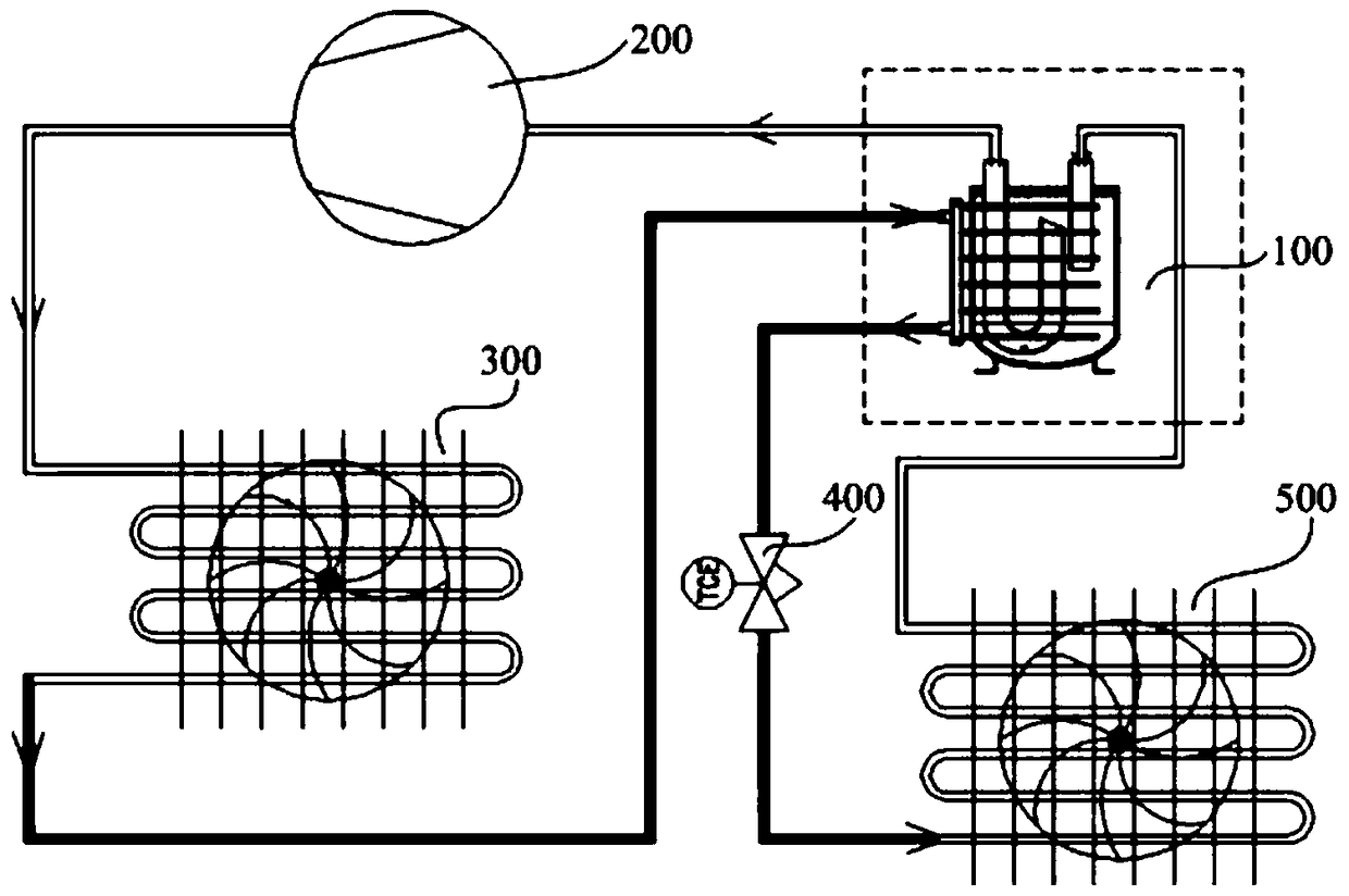
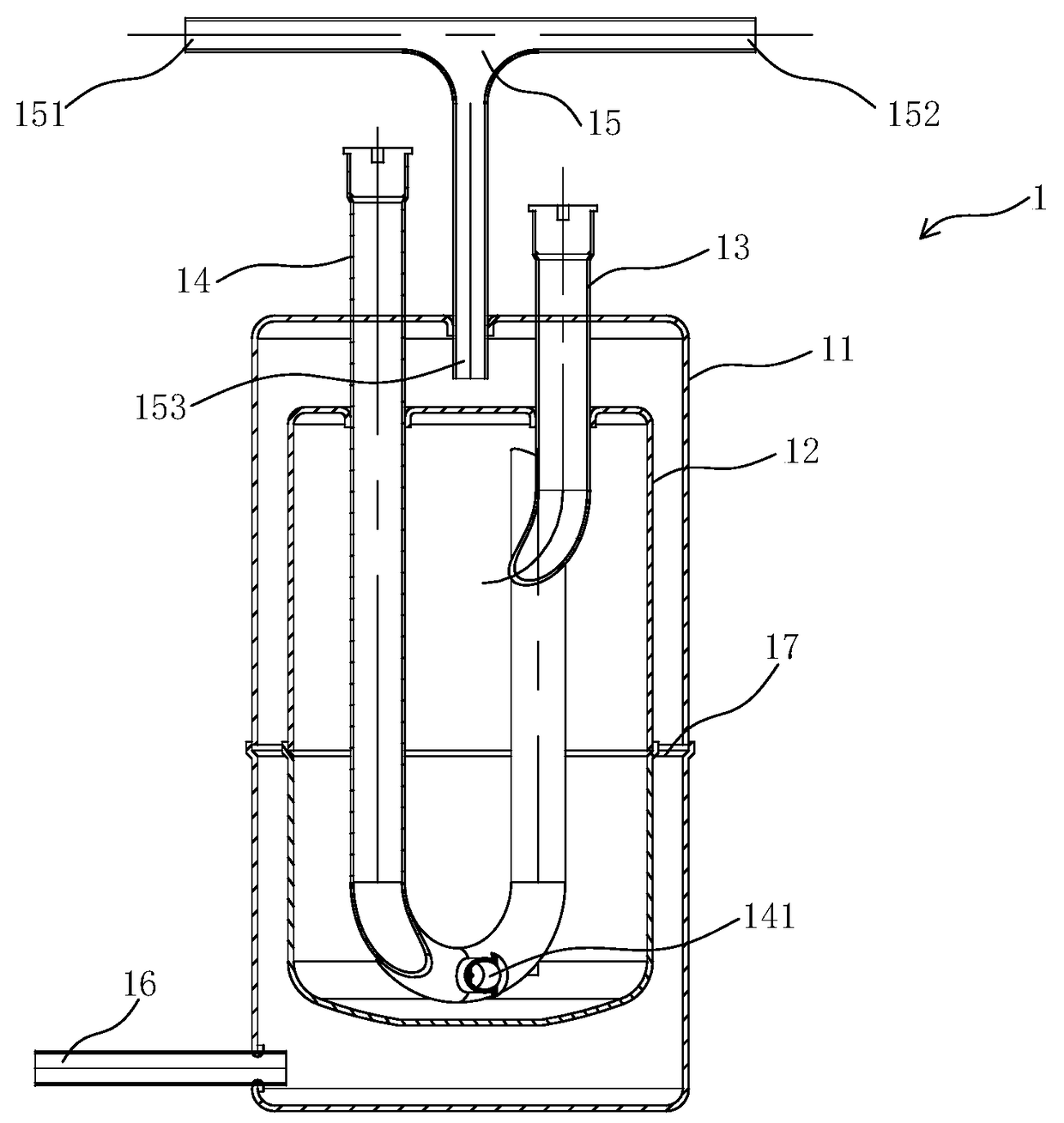
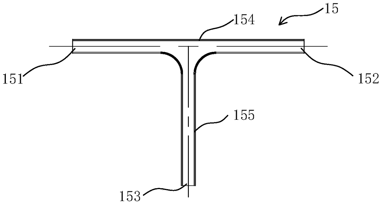
[0031] The technical solutions of the present invention will be further described below in conjunction with the accompanying drawings and through specific implementation methods.

[0032] In the description of the present invention, it should be understood that the orientation or positional relationship indicated by the terms "center", "length", "width", "top", "bottom", "inner" and "outer" are based on the attached The orientation or positional relationship shown in the figure is only for the convenience of describing the present invention and simplifying the description, and does not indicate or imply that the referred device or element must have a specific orientation, be constructed and operated in a specific orientation, and therefore cannot be interpreted as a reference to this invention. Invention Limitations.

[0033] In addition, the terms "first" and "second" are used for descriptive purposes only, and cannot be interpreted as indicating or implying relative importan...


PUM


Abstract

A gas liquid separator (1), comprising: sealed spaces separately formed by a housing (11) and an inner container (12), the inner container (12) being inside of the housing (11); the space between the housing (11) and the inner container (12) forms a supercooling passage, and the space inside of the inner container (12) forms a superheating passage; the superheating passage has a gas inlet pipe (13) for introducing in refrigerant steam and has a gas outlet pipe (14) for discharging the refrigerant steam out of the gas liquid separator (1); the supercooling passage has a liquid inlet pipe (15) for introducing in refrigerant liquid and has a liquid outlet pipe (16) for discharging the refrigerant liquid out of the gas liquid separator (1); the refrigerant liquid inside of the supercooling passage and the refrigerant steam inside of the superheating passage undergo heat exchange.

Description

technical field [0001] The invention relates to the technical field of air conditioning, in particular to a gas-liquid separator, an air-conditioning system including the gas-liquid separator, and an operating method of the air-conditioning system. Background technique [0002] When the air conditioning unit is in the cooling state, the refrigerant is compressed by the compressor and transformed into a high-temperature and high-pressure gas, and enters the outdoor heat exchanger (condenser) through the four-way valve. After the condenser absorbs cold and releases heat, it becomes a medium-temperature and high-pressure liquid. After the valve, it becomes a low-temperature and low-pressure liquid, and after the indoor heat exchanger (evaporator) absorbs heat and releases cooling, it becomes a low-temperature and low-pressure gas, returns to the compressor through the four-way valve, and then continues the cycle. When the air conditioning unit is in the heating state, the refri...

Claims


Application Information

Patent Timeline
Patent Type & Authority Patents(China)
IPC IPC(8): F25B43/00F25B29/00F24F1/00
CPCF25B43/00
Inventor 邹大枢李胤媛梁桂源罗智越位向前李慧玲
Owner GREE ELECTRIC APPLIANCES INC
Why Eureka
Try Eureka