Air-injection enthalpy-increasing heat pump air-conditioning system, control method, control device, and air conditioner

A technology of air injection to increase enthalpy and heat pump air-conditioning, which is applied in air-conditioning systems, heating methods, refrigeration and liquefaction, etc. It can solve problems that affect the service life of compressors, low exhaust and suction temperatures of compressors, and lack of oil in compressors, so as to avoid The effect of heat loss, increasing the suction superheat and ensuring the service life

Active Publication Date: 2019-08-30
GD MIDEA HEATING & VENTILATING EQUIP CO LTD +1
View PDF8 Cites 0 Cited by
  • Summary
  • Abstract
  • Description
  • Claims
  • Application Information

AI Technical Summary

Problems solved by technology

At the beginning of defrosting, the frequency of the compressor decreases, and the refrigerant flowing out of the gas-liquid separator decreases, resulting in an increase of liquid refrigerant in the gas-liquid separator; The ambient temperature is low and the condensation effect is good. As a result, during the defrosting process, the discharge and suction air temperature of the compressor is low, the superheat of the suction air is low, and the compressor is in a wet running state. In severe cases, the compressor will suffer from oil shortage and liquid shock. Seriously affect the service life of the compressor and reduce the reliability of the air conditioner operation

Method used


Image

  • Air-injection enthalpy-increasing heat pump air-conditioning system, control method, control device, and air conditioner
  • Air-injection enthalpy-increasing heat pump air-conditioning system, control method, control device, and air conditioner
  • Air-injection enthalpy-increasing heat pump air-conditioning system, control method, control device, and air conditioner

Examples


Embodiment Construction

[0038] In order to understand the above-mentioned purpose, features and advantages of the present invention more clearly, the present invention will be further described in detail below in conjunction with the accompanying drawings and specific embodiments. It should be noted that, in the case of no conflict, the embodiments of the present application and the features in the embodiments can be combined with each other.

[0039] In the following description, many specific details are set forth in order to fully understand the present invention. However, the present invention can also be implemented in other ways different from those described here. Therefore, the protection scope of the present invention is not limited by the specific details disclosed below. EXAMPLE LIMITATIONS.

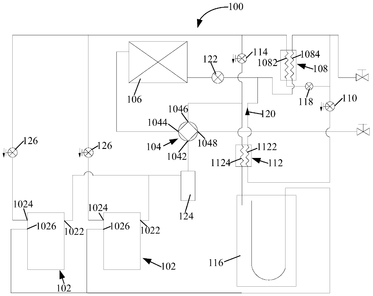
[0040] figure 1 A schematic structural view of an air injection heat pump air conditioning system according to an embodiment of the present invention is shown.

[0041] Such as figure 1 As shown, ...


PUM


Abstract

The present invention provides an air-injection enthalpy-increasing heat pump air conditioning system, a control method, a control device and an air conditioner, wherein the air-injecting enthalpy-increasing heat pump air-conditioning system includes: a compressor, including an exhaust port, an injection port and an air return port; a reversing assembly , including the first valve port to the fourth valve port; the outdoor heat exchanger; the first heat exchanger and the first solenoid valve, the first heat exchanger includes the first heat exchange flow path and the second heat exchange flow path; the second A heat exchanger and a second electromagnetic valve, the second heat exchanger includes a third heat exchange flow path and a fourth heat exchange flow path, the first end of the third heat exchange flow path is connected to the second end of the second heat exchange flow path end, the second end of the third heat exchange flow path is connected to the second end of the first electromagnetic valve, the first end of the fourth heat exchange flow path and the third valve port of the reversing assembly are connected to the second end of the second electromagnetic valve The first end, the second end of the second electromagnetic valve is connected to the first end of the first heat exchange flow path; and the gas-liquid separator. Through the technical scheme of the invention, the compressor can be prevented from running wet when the air conditioner is defrosting.

Description

technical field [0001] The present invention relates to the technical field of refrigeration and air conditioning, in particular to an air-injection enthalpy-increasing heat pump air-conditioning system, a control method for the air-injection enthalpy-increasing heat pump air-conditioning system, a control device and an air conditioner for the air-injection enthalpy-increasing heat pump air-conditioning system. Background technique [0002] When the air conditioner operates in the heating mode in winter, the outdoor ambient temperature is low, the temperature of the outdoor condenser is low, and frost occurs on the outdoor condenser, which reduces the heating effect. The outdoor condenser can be defrosted to improve the reliability and heating effect of the heat pump air conditioning system of the air conditioner during operation. [0003] In the related defrosting scheme, when the air conditioner does not stop, adjust the frequency of the compressor, and then switch to the ...

Claims


Application Information

Patent Timeline
Patent Type & Authority Patents(China)
IPC IPC(8): F24F5/00F24F11/84F24F11/89F24F11/65F25B29/00F25B13/00F25B41/04F25B49/02F25B47/02F25B41/00F25B41/20F25B41/40
CPCF24F1/0003F24F5/001F24F11/30F24F11/62F24F11/83F25B13/00F25B29/003F25B41/00F25B47/02F25B49/02F24F11/84F24F11/41F24F11/65F25B2313/02741F25B2600/25F25B2347/023F25B2341/001F25B41/20
Inventor 董文涛许永锋梁伯启薛晓王茹翰王威汪诗鹏
Owner GD MIDEA HEATING & VENTILATING EQUIP CO LTD
Why Eureka
Try Eureka