
Display device

Active Publication Date: 2017-08-31
JAPAN DISPLAY INC
View PDF6 Cites 6 Cited by
  • Summary
  • Abstract
  • Description
  • Claims
  • Application Information

AI Technical Summary

Benefits of technology

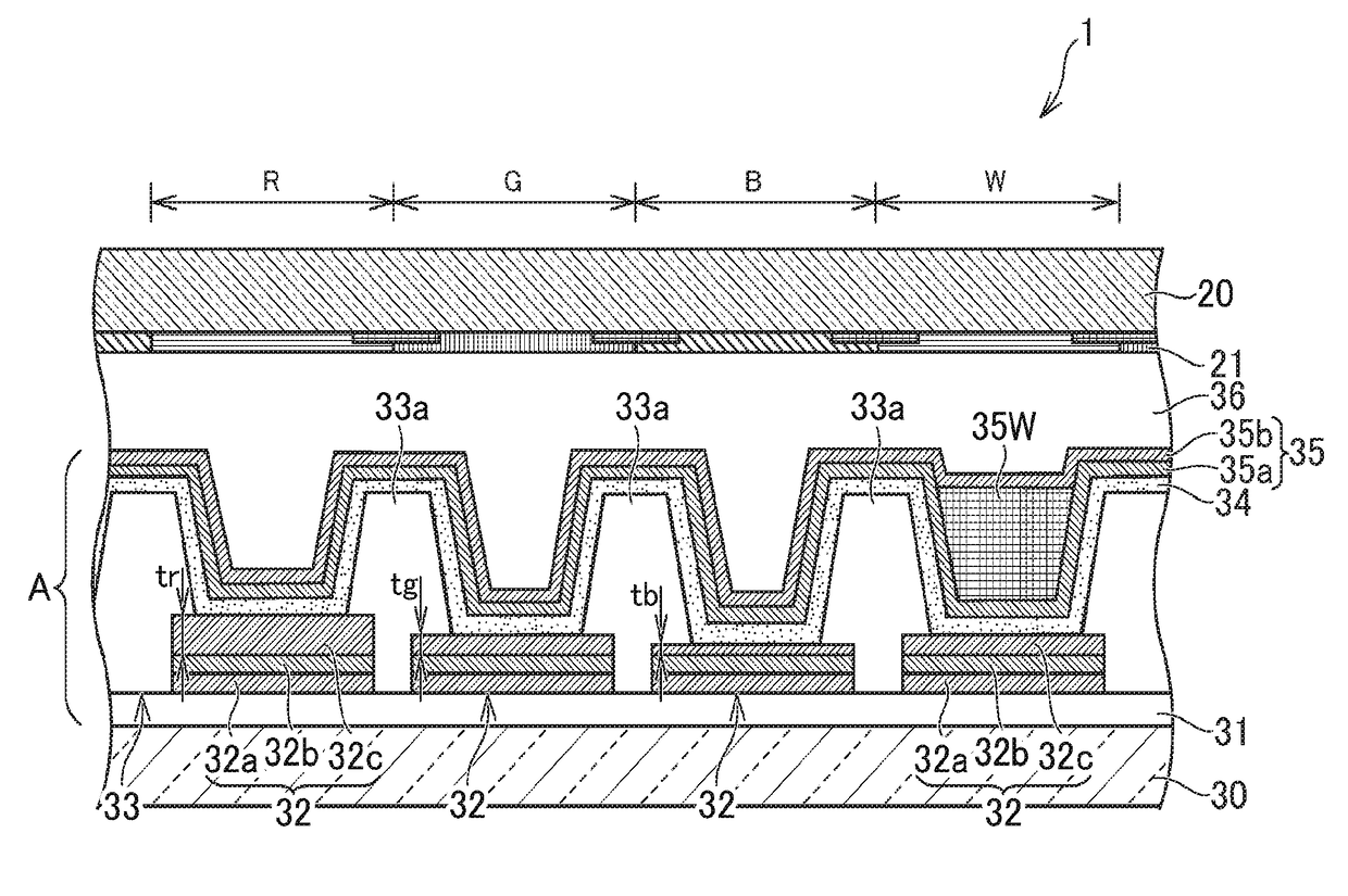
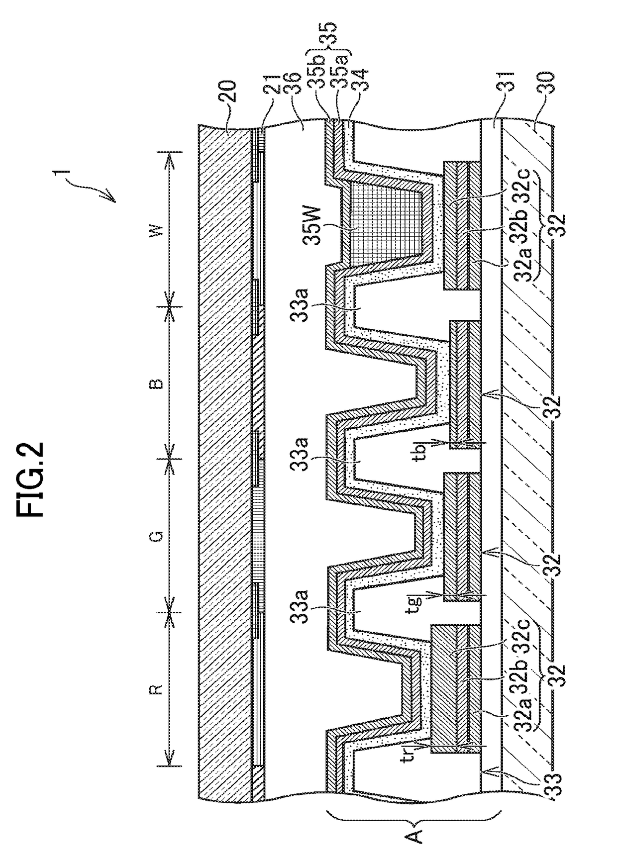
The patent aims to provide a display device that combines the benefits of white pixels and a micro-cavity structure without increasing manufacturing costs. White pixels have the advantage of emitting light with a pure color, while micro-cavity structures have the advantage of having high contrast and efficient lighting. The display device described in this patent achieves this by designing a structure that reduces optical interference in the white pixels and includes a micro-cavity structure in chromatic color pixels. The distance between the reflecting layers in the white pixels is larger than in the chromatic color pixels, and the second reflecting layer is formed on both white and chromatic color pixels. This avoids patterning the semitransparent reflecting layer in accord with the positions of the pixels, reducing manufacturing costs.

Problems solved by technology

The patterning process increases cost in manufacturing the device.

Method used


Image

  • Display device
  • Display device
  • Display device

Examples


Embodiment Construction

[0017]Hereinafter, embodiments according to the present invention will be described. In the present specification, an organic EL display device including an organic LED (Light Emitting Diode) as a light emitting element will be described as an example of the embodiments.

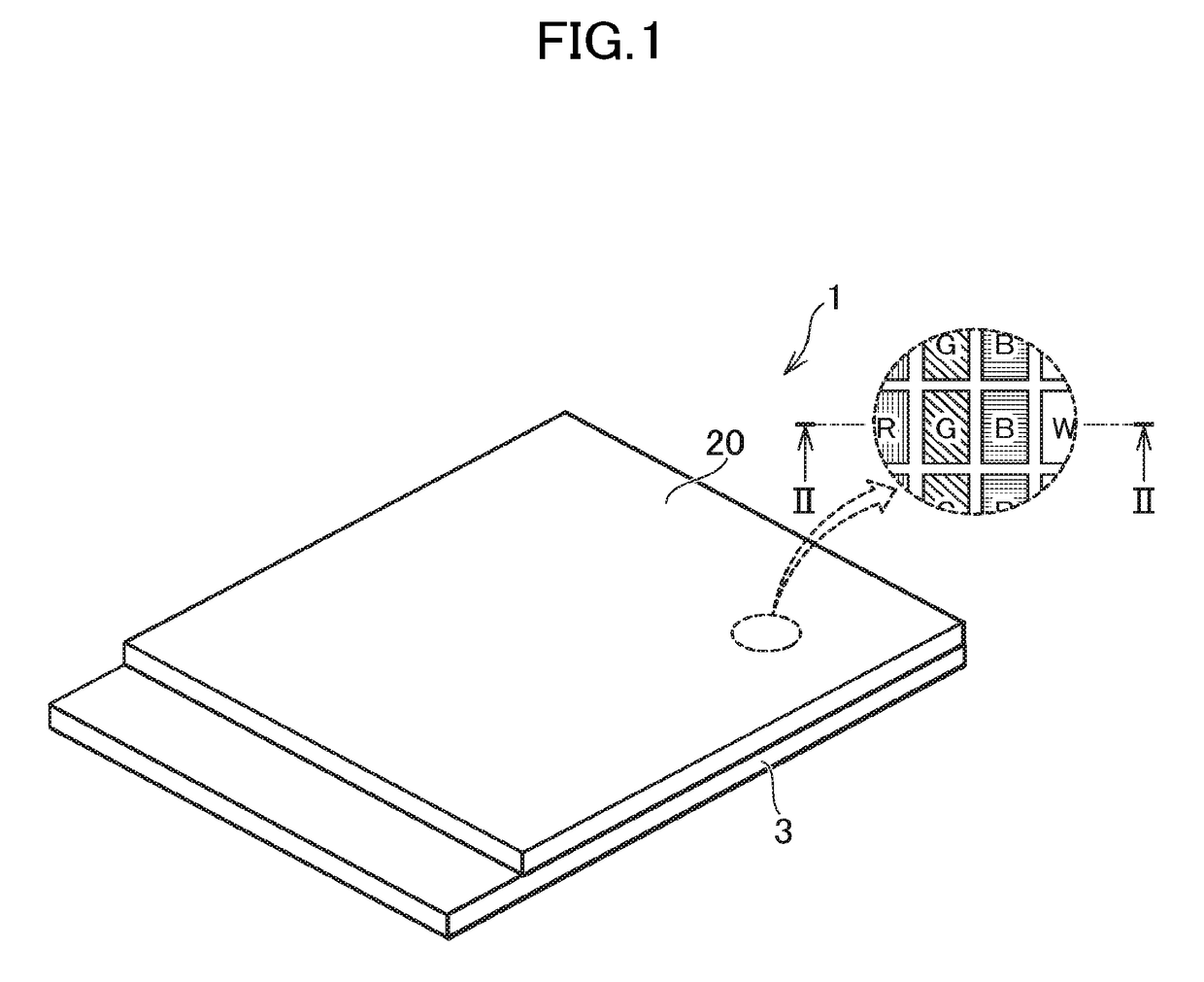
[0018]FIG. 1 illustrates an exemplary organic EL display device of the embodiments according to the present invention. FIG. 2 is a cross section taken along line II-II in FIG. 1. In the following description, an “upward direction” means a direction from the display panel 3 to the opposite substrate 20. On the contrary, a “downward direction” means a direction from the opposite substrate 20 to the display panel 3.

[0019]The present specification discloses examples of various embodiments according to the present invention. Embodiments which maintain the spirit of the present invention and are easily modified by those skilled in the art are surely contained in the scope of the invention. In addition, a width, a thickness...


PUM


Abstract

A reflecting layer is provided for each of a white pixel PW and a plurality of chromatic color pixels PR, PG and PB. A semitransparent reflecting layer is provided for each of the white pixel PW and the plurality of chromatic color pixels PR, PG and PB. The distance between the reflecting layer and the semitransparent reflecting layer in the white pixel PW is larger than the largest distance among distances between the reflecting layer and the semitransparent reflecting layer in the chromatic color pixels PR, PG, PB. Such display device can suppress increase in manufacturing cost and obtain both merits of optical micro-cavity structure and of the white pixel.

Description

CROSS-REFERENCE TO RELATED APPLICATION[0001]The present application claims priority from Japanese application JP2016-036010 filed on Feb. 26, 2016, the content of which is hereby incorporated by reference into this application.BACKGROUND OF THE INVENTION[0002]1. Field of the Invention[0003]The present patent specification relates to a display device and more particularly to a display device employing light-emitting elements such as organic electroluminescent (EL) elements in pixels[0004]2. Description of the Related Art[0005]Some organic EL display devices have an optical micro-cavity structure where a distance between a reflecting layer and a semitransparent reflecting layer in pixels is regulated according to wavelength of light emitted from a light emitting layer. In most of the devices, the reflecting layer and the semitransparent reflecting layer are employed as electrodes, and the light emitting layer is formed between the reflecting layer and the semitransparent reflecting la...

Claims


Application Information

Patent Timeline
IPC IPC(8): H01L27/32H01L51/52
CPCH01L27/3206H01L51/5265H01L27/322H01L51/5218H01L27/3213H01L51/5271H10K59/351H10K59/38H10K50/818H10K50/852H10K59/30H10K50/856
Inventor MAEDA, NORIHISAUSHIKUBO, TAKAHIRO
Owner JAPAN DISPLAY INC
Learn More