Contact pin and socket for electrical component

a technology of contact pins and sockets, applied in the direction of coupling contact members, coupling device connections, instruments, etc., can solve the problems of inability to electrically and appropriately connect first and second electrical components, and the buckle is liable to oscillate from side to side when shrunk, so as to achieve the effect of simple and accurate assembly

Inactive Publication Date: 2017-08-31
ENPLAS CORP
View PDF16 Cites 0 Cited by
  • Summary
  • Abstract
  • Description
  • Claims
  • Application Information

AI Technical Summary

Benefits of technology

[0006]The present invention aims at providing a contact pin and a socket for electrical components which can avoid a situation where the first and second electrical components cannot be appropriately connected due to lack of contact pressure in electrically connecting the electrical components with each other.
[0011]According to the present invention, the first and second plungers are mutually conducted via the contact piece when the first electrical component is electrically connected to the second electrical component each other, and the expansion and shrinkage operation of the meander portion is guided by the contact piece when the meander portion of the second plunger is expanded and / or shrunk. Accordingly, the meander portion can be prevented from oscillating from side to side when the meander portion is shrunk. As a result, this can avoid such a situation that the electrical components cannot be appropriately connected to each other because of lack of contact pressure when the first and second electrical components are electrically connected by the contact pin.
[0013]According to the present invention, the engaging portion is engaged with the engageable portion to guide the vertical movement of the second plunger with respect to the first plunger, which enables the contact pin to be simply and accurately assembled.

Problems solved by technology

In such a contact pin, however, the bellows is liable to oscillate from side to side when shrunk.
In this case, force for elastically urging the stationary and movable portions is decreased in the direction of separating them from each other to make insufficient a contact pressure between the first and second electrical components and the contact pin, which causes a problem that the first and second electrical components cannot be electrically and appropriately connected.

Method used


Image

  • Contact pin and socket for electrical component
  • Contact pin and socket for electrical component
  • Contact pin and socket for electrical component

Examples


first embodiment

[0031]FIGS. 1 to 7B show the present invention.

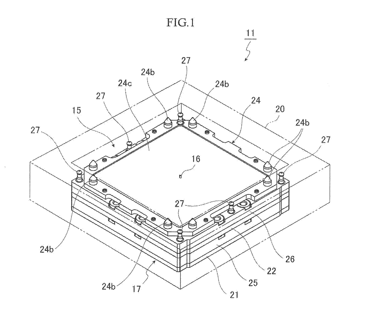
[0032]FIG. 1 shows an IC socket 11 being “a socket for electrical components” according to the first embodiment. The IC socket 11 is arranged on a wiring substrate 13 (refer to FIG. 6B) being a “first electrical component”, and electrically connects a spherical terminal 12a of an IC package 12 being a “second electrical component” with a pad 13a of the wiring substrate 13. The IC package 12 is housed in the IC socket 11 to conduct a burn-in test for the IC package 12.

[0033]The IC package 12 is called a ball grid array (BGA) type, includes a package main body 12b with a square shape when viewed from the top and is configured such that a plurality of spherical terminals 12a (refer to FIG. 7B) are arranged in a lattice shape on the lower surface of the package main body 12b and projected downward. In FIG. 7B, only one of the plurality of spherical terminals 12a is shown.

[0034]As shown in FIG. 1, the IC socket 11 includes a contact module 1...


PUM


Abstract

A contact pin to electrically connect a first electrical component to a second electrical component and contact with the first and second electrical components at a sufficiently large contact pressure. The contact pin includes a first plunger with a first contact portion and a second plunger with a second contact portion. An expandable meander portion is formed on the second plunger. A contact piece to conduct electricity between the first and second plungers is provided to guide the expanding and shrinking operation of the meander portion. The first and second plungers are conducted via the contact piece when the first electrical component is electrically connected to the second electrical component, and the meander portion is shrunk to bring the first contact portion of the first plunger and the second contact portion of the second plunger into contact with the first and second electrical components at a sufficiently large contact pressure.

Description

BACKGROUND OF THE INVENTION[0001]Field of Invention[0002]The present invention relates to a contact pin (a contact member) for electrically connecting first and second electrical components with each other, used as a probe for inspecting electrical components, for example, and a socket for the electrical components with the contact pin.[0003]Description of the Related Art[0004]Up to now, as the contact pin of this type, there has been known the one that stationary portion and movable portion are coupled together by a bellows which can expand and shrink in up and down directions and a stick-shaped movable contact piece is provided on the movable portion along the bellows to secure a desired conduction with a predetermined displacement ensured (refer to Japanese Patent Laid-Open No. 2013-89373, for example). In using the contact pin, the movable portion is depressed toward the stationary portion to shrink the bellows, bring the movable contact piece into contact with the stationary po...

Claims


Application Information

Patent Timeline
Patent Type & Authority Applications(United States)
IPC IPC(8): H01R13/24H01R12/71
CPCH01R12/716H01R13/2428G01R1/06722H01R13/2485
Inventor HACHUDA, OSAMU
Owner ENPLAS CORP
Why Eureka
Try Eureka