Helicopter Anti-Torque Rotor

a technology of anti-torque rotor and helicopter, which is applied in the direction of rotors, aircraft components, aircrafts, etc., can solve the problems of fouling inside the anti-torque rotor, complicated production, assembly and maintenance,

Active Publication Date: 2017-09-07
LEONARDO SPA
View PDF0 Cites 16 Cited by
  • Summary
  • Abstract
  • Description
  • Claims
  • Application Information

AI Technical Summary

Benefits of technology

[0040]It is an object of the present invention to provide a helicopter designed to meet at least one of the above demands cheaply and easily.

Problems solved by technology

In particular, the known hydraulic actuator described comprises a large number of component parts, and is therefore complicated to produce, assemble and maintain.
The actuator described also inevitably results in fouling inside the anti-torque rotor, mainly due to the hydraulic motor oil supply and the need to keep it pressurized.

Method used


Image

  • Helicopter Anti-Torque Rotor
  • Helicopter Anti-Torque Rotor
  • Helicopter Anti-Torque Rotor

Examples


Embodiment Construction

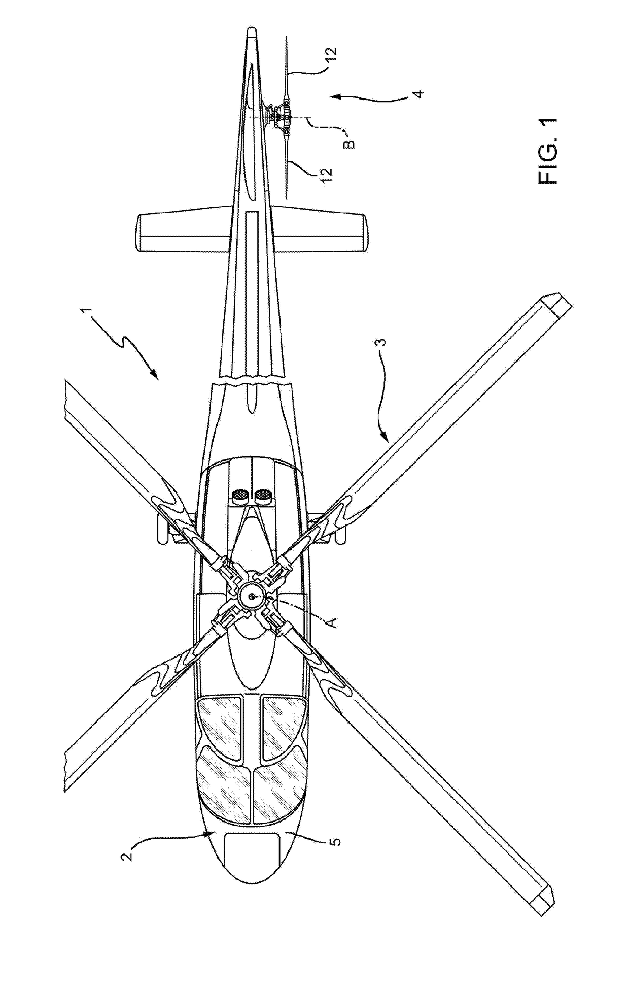
[0050]Number 1 in FIG. 1 indicates a helicopter substantially comprising a fuselage 2 with a nose 5; a main rotor 3 fitted to the top of fuselage 2 and rotatable about an axis A; and an anti-torque tail rotor fitted to a fin projecting from fuselage 2 at the opposite end to nose 5.

[0051]More specifically, main rotor 3 provides helicopter 1 with the lift to raise it, and the thrust to move it forward, while rotor 4 exerts force on the fin to generate a straightening torque on fuselage 2. The straightening torque balances the torque exerted on fuselage 2 by main rotor 3, and which would otherwise rotate fuselage 2 about axis A.

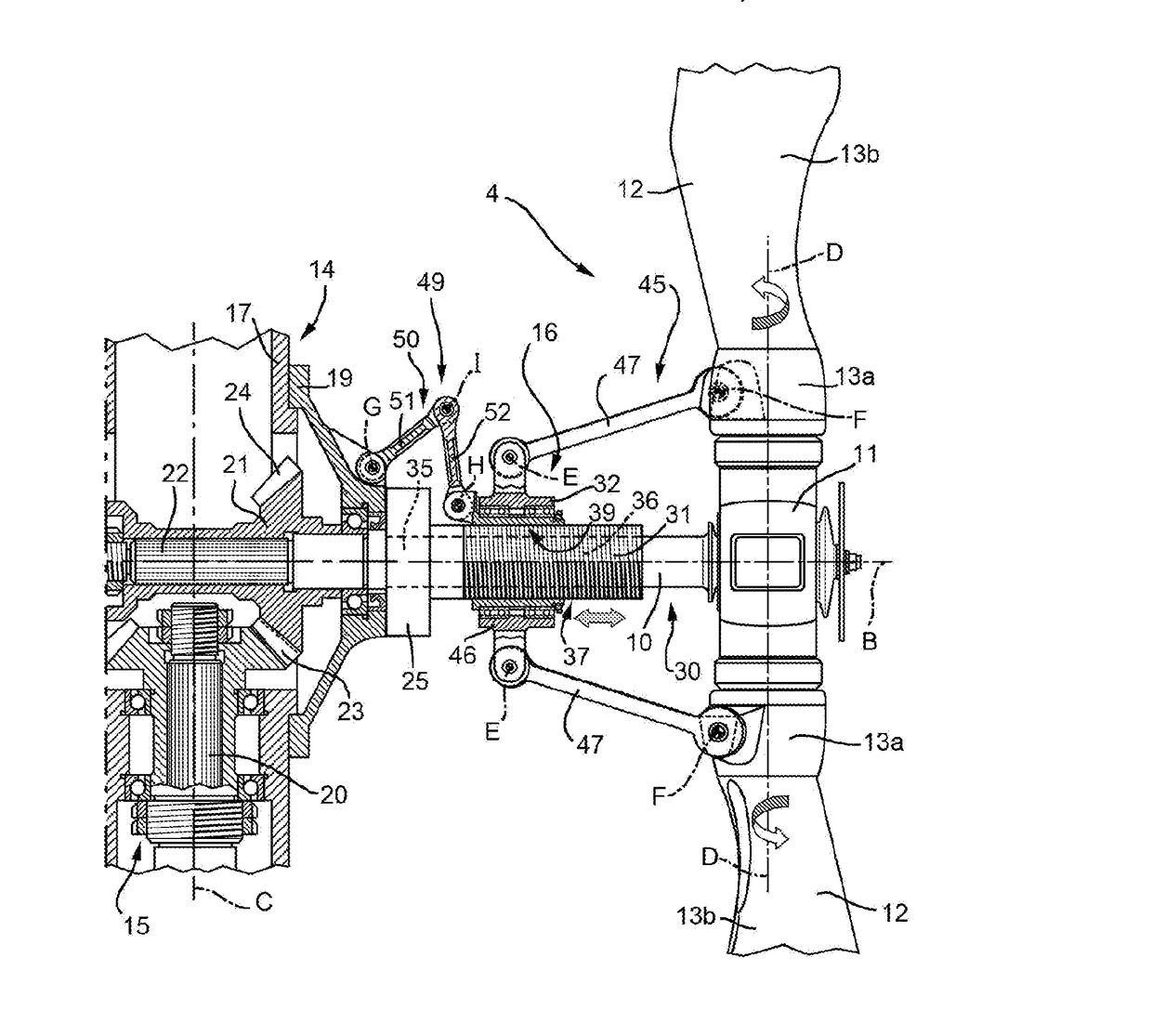
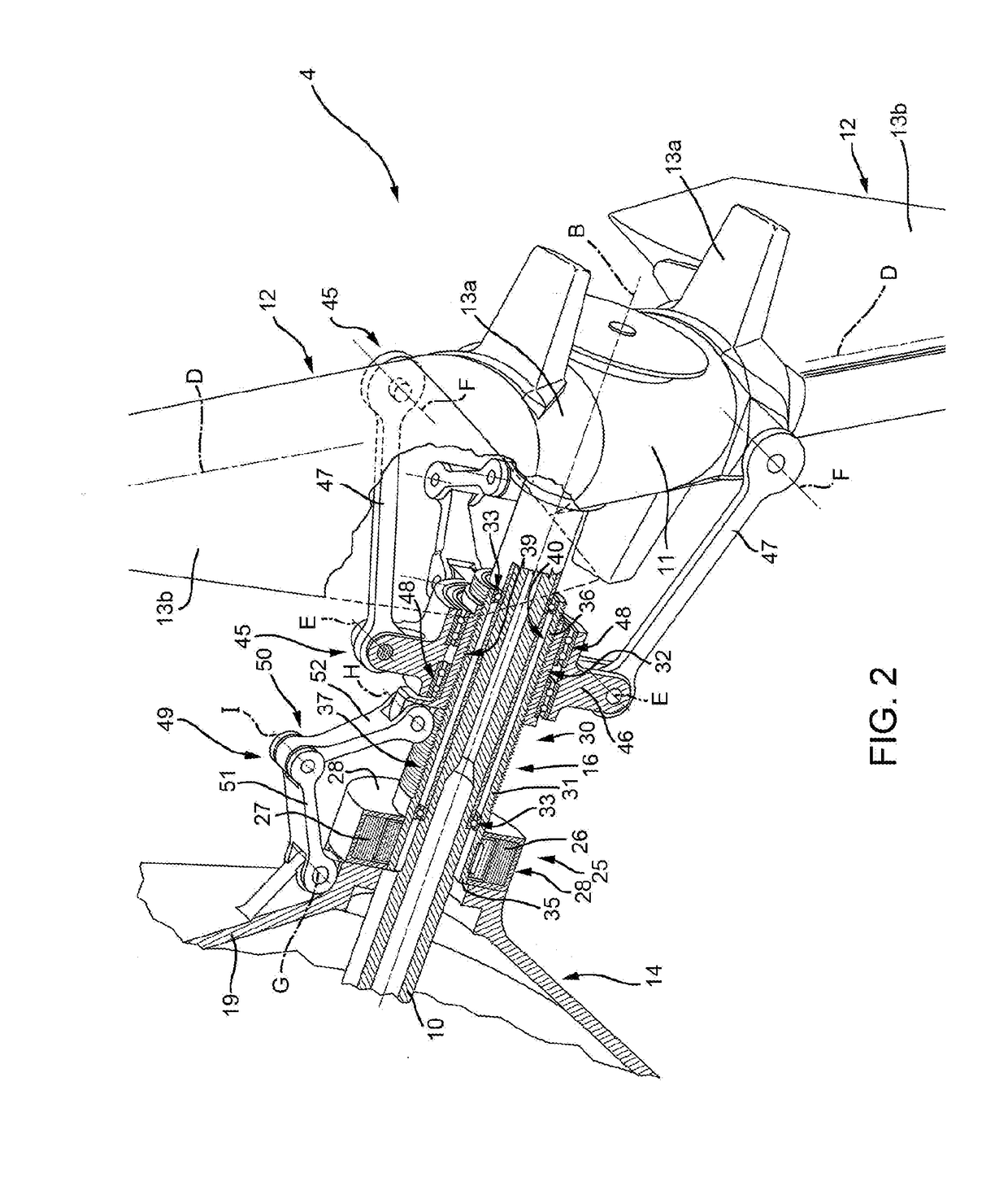
[0052]Rotor 4 substantially comprises (FIGS. 2 to 5):[0053]a drive shaft 10 which rotates about an axis B crosswise to the axis of rotation A of main rotor 3;[0054]a hub 11 fixed angularly with respect to shaft 10 about axis B; and[0055]two blades 12 which project from hub 11, on opposite sides of axis B, are fixed angularly with respect to hub 11 about axis B, ...


PUM


Abstract

An anti-torque rotor of a helicopter, having: a supporting body; a drive shaft which rotates about a first axis with respect to the supporting body; a hub connected operatively to drive shaft and angularly fixed with respect to first axis; at least one blade which is connected operatively to hub, is angularly fixed with respect to first axis, and is angularly movable with respect to a second axis to adjust the pitch angle of blade; and an actuator which can be operated to rotate blade about second axis to adjust the pitch angle of blade; actuator has an electric motor which generates torque along the first axis; and a mechanical stage interposed between the electric motor and blade, and designed to convert the torque into rotation of blade about the respective second axes; electric motor is fixed to supporting body.

Description

CROSS-REFERENCE TO RELATED APPLICATIONS[0001]This application is a National Stage Application of International Patent Application No. PCT / IB2015 / 056031, filed Aug. 7, 2015, which claims the benefit of, and priority to, European Patent Application No. 14425106.3, filed Aug. 8, 2014, the contents of these applications being incorporated entirely herein by reference.TECHNICAL FIELD[0002]The present invention relates to a helicopter anti-torque rotor.BACKGROUND ART[0003]Helicopters are known comprising a fuselage; a main rotor fitted to a top centre portion of the fuselage; and an anti-torque tail rotor for counteracting the torque transmitted from the main rotor to the fuselage.[0004]Anti-torque tail rotors substantially comprise:[0005]a drive shaft which rotates about a first axis;[0006]a hub connected operatively to the drive shaft so as to also rotate about the first axis; and[0007]a number of blades which rotate integrally with the hub about the first axis, project from the hub, an...

Claims


Application Information

Patent Timeline
Patent Type & Authority Applications(United States)
IPC IPC(8): B64C27/82B64C27/68B64C27/78
CPCB64C27/82B64C27/78B64C27/59B64C27/54B64C27/58B64C27/68B64C11/44
Inventor WANG, JAMES
Owner LEONARDO SPA
Why Eureka
Try Eureka