
Ribbon spring of a sprag type one-way clutch and sprag type one-way clutch

a one-way clutch, sprag-type technology, applied in the direction of clutches, freewheel clutches, actuators, etc., can solve the problems of abnormal wear, damage, or even destruction, and become impossible to apply to the corresponding sprags, so as to achieve smooth slide, prevent damage to the tongue effectively, and operate reliably

Inactive Publication Date: 2017-09-07
NTN CORP
View PDF2 Cites 2 Cited by
  • Summary
  • Abstract
  • Description
  • Claims
  • Application Information

AI Technical Summary

Benefits of technology

The patent describes a device that includes a strip that is bent in a circular shape. The strip has individuals called "tongues" that are attached to it. These tongues have a V-shaped bend in the middle, which allows them to bend smoothly inward when the device is in use. This design helps to prevent damage to the tongues. Additionally, there may also be bent portions on the sides of each pocket to make it easier to bend the strip into a circular shape. The technical effect of this design is to improve the durability and reliability of the device.

Problems solved by technology

If the friction coefficient at the slide contact portions of the tongues and the sprags is large, the tongues cannot smoothly slide on the sprags, and could be damaged, or even destroyed, by getting stuck in the circumferential direction, especially if the inner and outer rings are rotating at a high speed when the sprags disengage from the inner and outer rings, thereby allowing the inner ring, which has been locked to the outer ring through the sprags, to rotate independently of the outer ring.
If one or some of the tongues are damaged, it becomes impossible to apply to the corresponding sprags a moment that tends to bring these sprags into contact with the inner and outer rings.
This results in the other sprags being brought into engagement with the inner and outer rings under higher surface pressures, which could cause abnormal wear, and thus peeling, at the portions where the other sprags engage the inner and outer rings.
Also, if one or some of the tongues are damaged, pieces of the damaged tongues could become wedged between the sprags and the inner and / or outer rings such that the sprags cannot disengage from the inner and outer rings.

Method used


Image

  • Ribbon spring of a sprag type one-way clutch and sprag type one-way clutch
  • Ribbon spring of a sprag type one-way clutch and sprag type one-way clutch
  • Ribbon spring of a sprag type one-way clutch and sprag type one-way clutch

Examples


Embodiment Construction

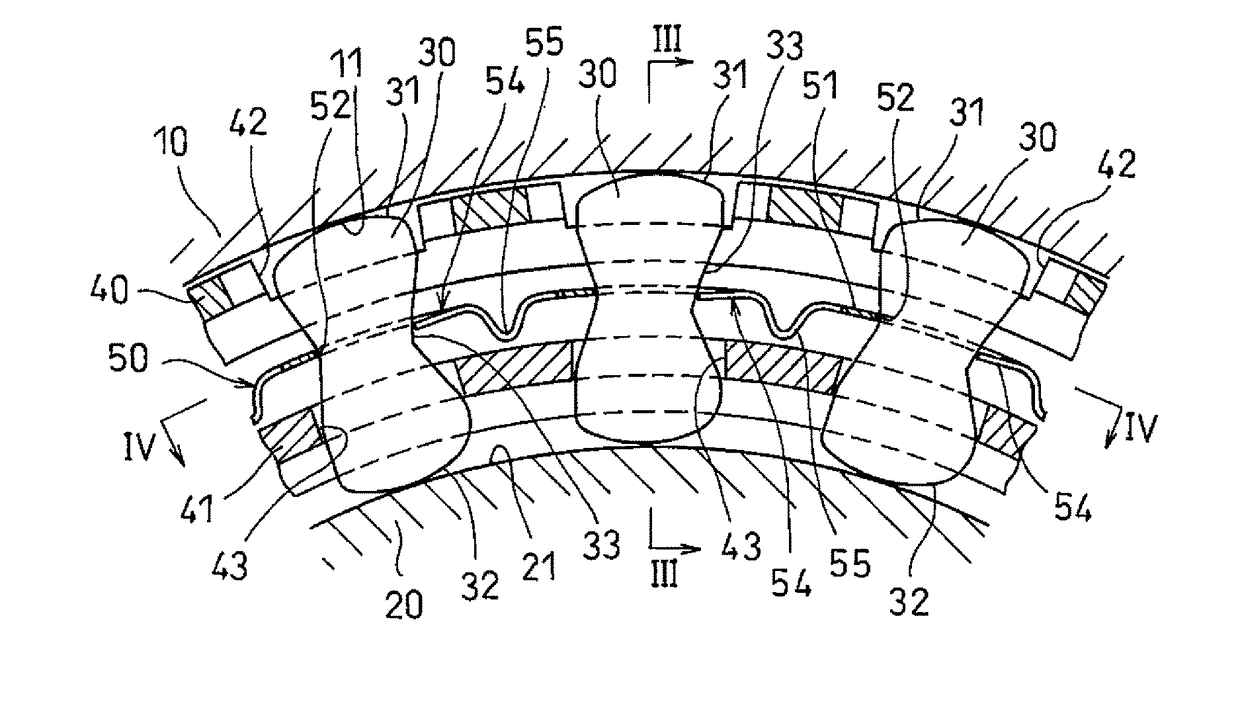
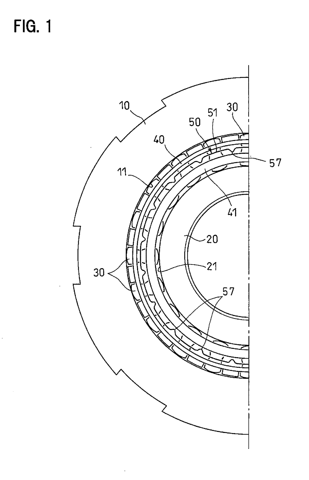
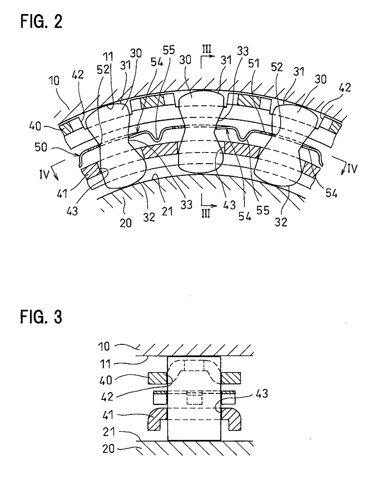
[0026]Now referring to the drawings, a sprag type one-way clutch embodying the present invention includes, as shown in FIGS. 1 and 2, an outer ring 10 and an inner ring 20 located inside of the outer ring 10. A plurality of sprags 30 are mounted between the outer ring 10 and the inner ring 20. Also mounted between the outer ring 10 and the inner ring 20 are an outer retainer 40 and an inner retainer 41 that retain the sprags 30. A ribbon spring 50 is mounted between the outer retainer 40 and the inner retainer 41.

[0027]The outer ring 10 has a cylindrical radially inner surface 11, while the inner ring 20 has a cylindrical radially outer surface 21. The sprags 30 are cocoon-shaped members each having, at one end thereof, an outer ring-side cam surface 31 configured to be selectively brought into and out of engagement with the radially inner surface 11 of the outer ring 10, and at the other end thereof, an inner ring-side cam surface 32 configured to be selectively brought into and ou...


PUM


Abstract

A ribbon spring of a sprag type one-way clutch is an elongated strip of sheet metal, and includes a plurality of pockets formed by punching so as to be spaced apart from each other in the longitudinal direction of the strip, to define bridges between respective adjacent pairs of the pockets. A tongue protrudes from one circumferential side of each bridge. The strip is mounted between an outer ring and an inner ring, while being bent in a circular shape such that sprags inserted in the respective pockets are biased by the respective tongues in the direction in which the sprags engage. Each tongue has a cut surface formed by shearing at its distal end, and including a droop. The strip is bent in the circular shape such that each droop is located on the radially outer side of the cut surface, and in contact with the sprag.

Description

TECHNICAL FIELD[0001]The present invention relates to a ribbon spring of a sprag type one-way clutch for use in e.g., a torque converter of a motor vehicle, and a sprag type one-way clutch including such a ribbon spring.BACKGROUND ART[0002]This type of sprag one-way clutch includes, as disclosed in the below-identified Patent documents 1-3, a plurality of sprags mounted between an outer ring and an inner ring, and retained by an outer retainer and an inner retainer mounted between the outer ring and the inner ring. The sprags are biased by a ribbon spring mounted between the outer retainer and the inner retainer in a direction in which an outer ring-side cam surface and an inner ring-side cam surface formed on the respective ends of each sprag are brought into contact with the outer ring radially inner surface and the inner ring radially outer surface, respectively.[0003]The ribbon spring comprises an elongated strip of sheet metal having a plurality of pockets formed by punching so...

Claims


Application Information

Patent Timeline
Patent Type & Authority Applications(United States)
IPC IPC(8): F16D41/07
CPCF16D41/07F16D2250/003F16D2250/0023F16D2041/0605
Inventor FUKAMI, RINO
Owner NTN CORP
Learn More