
E-vaping device cartridge with internal conductive element

a technology of conductive elements and cartridges, which is applied in the direction of electrical equipment, tobacco, other medical devices, etc., can solve the problems of overheating condition of the cartridge, and increased temperature in one or more portions of the cartridg

Active Publication Date: 2017-09-14
AKRIA CLIENT SERVICES LLC
View PDF13 Cites 53 Cited by
  • Summary
  • Abstract
  • Description
  • Claims
  • Application Information

AI Technical Summary

Benefits of technology

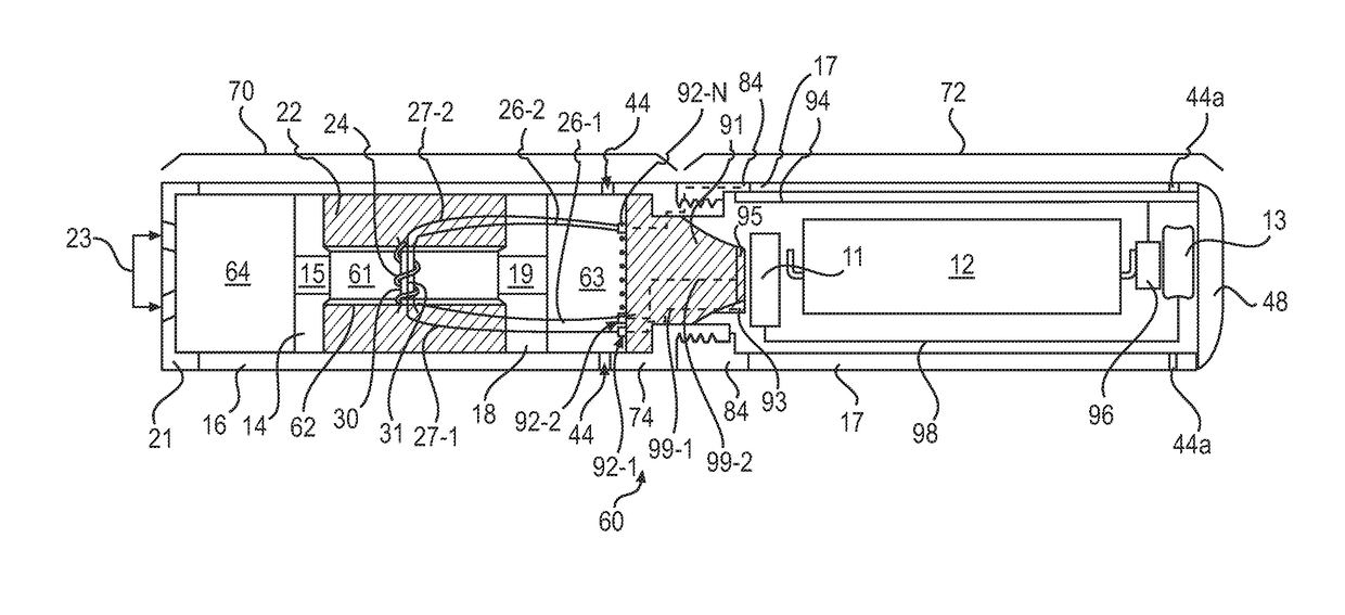
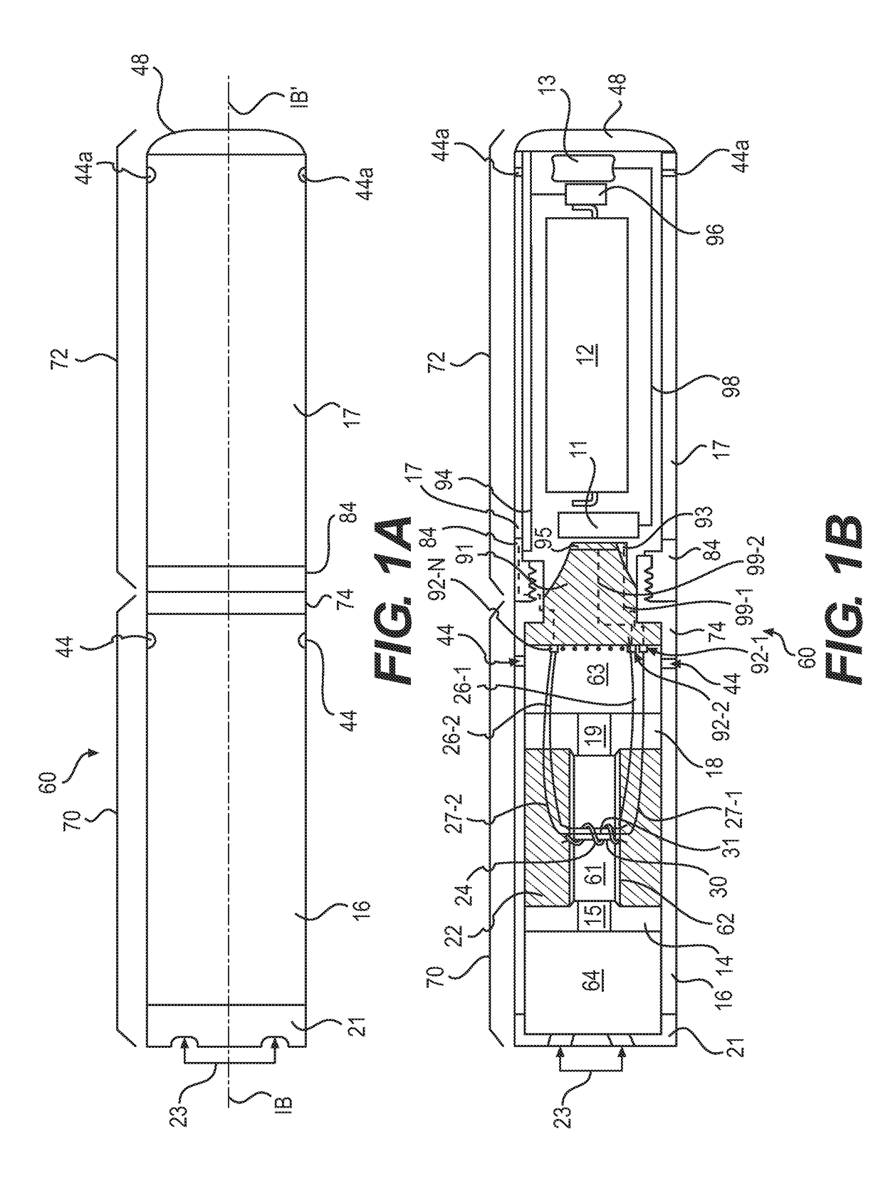
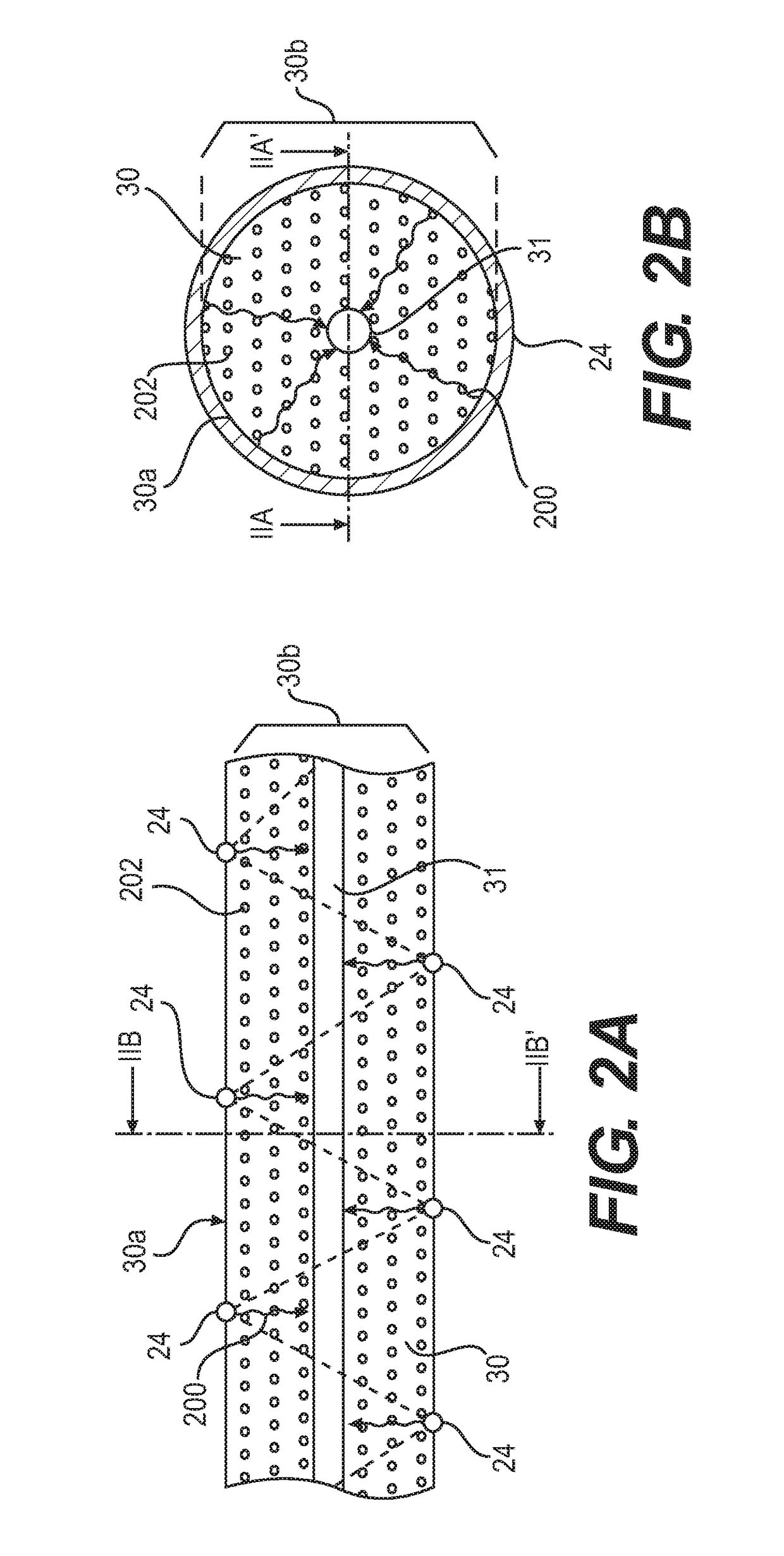
The patent describes a cartridge for an e-vaping device that includes a reservoir for holding a pre-vapor formulation, a dispensing interface for drawing the formulation, a heating element for heating the formulation, and a conductive element extending through the dispensing interface. The conductive element may be woven through the fibrous wicking material of the dispensing interface. The cartridge may also include a sensor wire separate from the conductive element and the heating element to carry a bridge electrical circuit. The control circuitry may be configured to determine the electrical resistance of the conductive element and control the power supplied to the heating element based on the resistance. The technical effect of this design is to provide a more efficient and effective heating of the pre-vapor formulation for inhalation by the user.

Problems solved by technology

In some cases, the heating element may generate excess heat, which may result in an increased temperature in one or more portions of the cartridge.
The heating element may generate excess heat due to receiving excessive power for vapor generation.
Excessive heat, internal temperatures, etc. may result in an overheat condition in the cartridge.
Overheating of the cartridge may result in degradation of one or more of the pre-vapor formulations, formation of one or more reaction products which may detract from the sensory experience when included in a vapor, etc.

Method used


Image

  • E-vaping device cartridge with internal conductive element
  • E-vaping device cartridge with internal conductive element
  • E-vaping device cartridge with internal conductive element

Examples


Embodiment Construction

[0042]Some detailed example embodiments are disclosed herein. However, specific structural and functional details disclosed herein are merely representative for purposes of describing example embodiments. Example embodiments may, however, be embodied in many alternate forms and should not be construed as limited to only the example embodiments set forth herein.

[0043]Accordingly, while example embodiments are capable of various modifications and alternative forms, example embodiments thereof are shown by way of example in the drawings and will herein be described in detail. It should be understood, however, that there is no intent to limit example embodiments to the particular forms disclosed, but to the contrary, example embodiments are to cover all modifications, equivalents, and alternatives falling within the scope of example embodiments. Like numbers refer to like elements throughout the description of the figures.

[0044]It should be understood that when an element or layer is re...


PUM


Abstract

A cartridge for an e-vaping device includes a conductive element extending through an interior of a dispensing interface to which a heating element is coupled. The conductive element may have a greater temperature coefficient of electrical resistivity than the heating element. The dispensing interface may include a fibrous wicking material, and the conductive element may be woven through an interior of the fibrous wicking material. A temperature of the dispensing interface may be determined based on monitoring an electrical resistance of the conductive element. An amount of pre-vapor formulation may be determined based on an electrical resistance of the bridge electrical circuit to an electrical signal between the heating element and the conductive element through the dispensing interface.

Description

BACKGROUND[0001]Field[0002]One or more example embodiments relate to electronic vaping and / or e-vaping devices.[0003]Description of Related Art[0004]E-vaping devices, also referred to herein as electronic vaping devices (EVDs) may be used by adult vapers for portable vaping. An e-vaping device may vaporize a pre-vapor formulation to form a vapor. The e-vaping device may include a reservoir that holds a pre-vapor formulation and a heating element that vaporizes the pre-vapor formulation by applying heat to at least a portion of the pre-vapor formulation.[0005]In some cases, the heating element may generate excess heat, which may result in an increased temperature in one or more portions of the cartridge. The heating element may generate excess heat due to receiving excessive power for vapor generation. In some cases, the excess heat may be due to a reduction in the amount of pre-vapor formulation in the cartridge. Excessive heat, internal temperatures, etc. may result in an overheat ...

Claims


Application Information

Patent Timeline
Patent Type & Authority Applications(United States)
IPC IPC(8): A24F47/00H05B1/02A24F40/10A24F40/42A24F40/53
CPCA24F47/008H05B1/0244A24F40/10A24F40/53A24F40/42H05B3/44A24F40/51A24F40/57A24F40/65A24F40/60A24F40/20A61M2205/3368A61M2205/50A61M2205/52A24F47/00
Inventor SMITH, BARRY S.CADIEUX, EDCOBLER, PATRICK
Owner AKRIA CLIENT SERVICES LLC
Learn More