Surgical eye shield

a technology of eye shield and surgical technique, applied in the field of perioperative eye shield, can solve the problems of trauma, surgeons, anaesthetists, nurse or other medical practitioners may lean on or place instruments, and the surgeon, anaesthetist, etc., and achieve the effect of increasing the rigidity of the eye shield and facilitating the insertion

Inactive Publication Date: 2017-09-14
INNOVGAS PTY LTD
View PDF7 Cites 5 Cited by
  • Summary
  • Abstract
  • Description
  • Claims
  • Application Information

AI Technical Summary

Benefits of technology

[0027]The transparent cover plate is strong enough to resist pressure being routinely applied to it in a medical situation. The transparent cover plate may also include ridges to increase the rigidity of the eye shield. In one form the ridges are generally perpendicular to the longitudinal axis of the eye shield. The transparent cover plate may also include grooves that extend down a front or rear, which permit greater flexing of the transparent cover plate, especially adjacent the temples of the patient.
[0028]Preferably the resiliently deformable base includes two spaced apart apertures extending therethrough that can be positioned by a user to correspond to the location of eye sockets of the patient. The resiliently deformable base further includes an adhesive central part that can be positioned to correspond to the location of the bridge of the patient's nose, to thereby create respective chambers to protect the eyes from direct contact, when the eye shield is attached to the face of the patient. By resiliently deformable the reader should understand that the base may be deformed, but has a tendency to expand back to, or close to, its original shape. This so called ‘memory’ of the material means that it tends to regain its original shape when not under pressure, and therefore is useful in conforming to the contoured surface around the eyes of the patient.

Problems solved by technology

If the medical procedure is being undertaken in or on the upper half of the body there is a considerable risk that a surgeon, anaesthetist, nurse or other medical practitioner may lean on or place instruments on the face and inadvertently the eye region of the patient.
Accordingly, if direct pressure is inadvertently applied to the patient's eye or eyes, trauma can occur.
This may be temporary loss or reduction of vision, bruising or may result in eye globe trauma leading to transient or permanent damage.
This however means that the eyelids are not visible during the medical procedure and may open without the knowledge of the medical practitioner.
The opening of the eyes may lead to injury or irritation of the patient's eye by corneal drying or abrasion.
Furthermore the eye pads do not prevent direct pressure being applied to the eye globes but simply reduces the degree of force, which may still be insufficient to avoid eye trauma.
There are however a number of problems with such designs.
Firstly, the strap has to be tight enough to hold the mask in place during the medical procedure and therefore the strap can cut into the ears and head of the patient.
Furthermore, the use of a strap is problematic in that it can be easily caught or displaced, especially when a patient is being rolled onto their side, as occurs in some medical procedures.
These moulded eye covers however protrude excessively outwardly from the face of the patient, which increases the likelihood that the shield would be bumped during the medical procedure.
Furthermore, the edges of the moulded eye covers are curved inwardly towards the edges of the eye sockets, which means they may impinge upon the eye when pressure is applied to the front of the cover.
Another limitation with the eye cover disclosed in CRAIG is that since the distance between the bulbous eye covers is fixed, and the bulbous eye covers must be positioned directly over respective eyes of the patient, there is only a very limited range of face sizes that the eye guard will accurately fit.
This inability of the face guard of CRAIG to fit multiple face sizes and shapes, is a significant problem.
Furthermore, the separate eye guards would interfere with eye patches used to hold the eyelids closed during surgery.

Method used


Image

  • Surgical eye shield
  • Surgical eye shield
  • Surgical eye shield

Examples


Embodiment Construction

[0067]Similar reference characters indicate corresponding parts throughout the drawings. Dimensions of certain parts shown in the drawings may have been modified and / or exaggerated for the purposes of clarity or illustration.

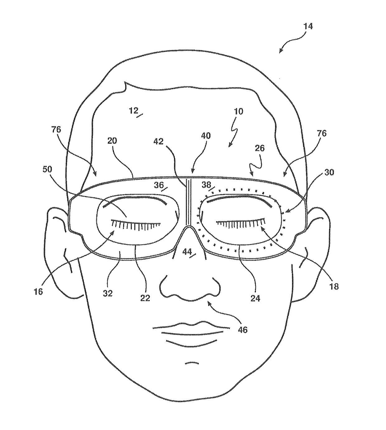
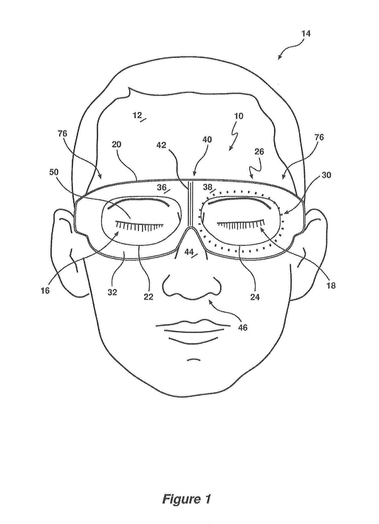
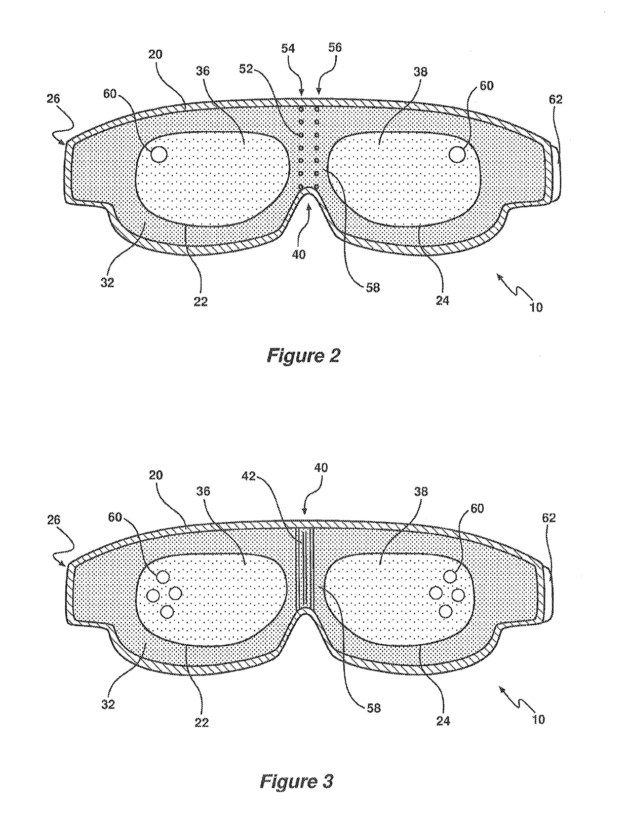
[0068]Referring to the drawings for a more detailed description, an improved surgical eye shield 10 is illustrated, demonstrating by way of examples, arrangements in which the principles of the present invention may be employed. The figures illustrate an eye shield 10 for releasable mounting to a face 12 of a patient 14, used to inhibit pressure being applied to eyes 16, 18 of the patient 14 during a medical procedure.

[0069]The reader should understand that the term eye or eyes used throughout the specification, unless otherwise stated, relates to the eye region in general including the eyelids, eye globe and cornea. Furthermore, the term pressure should be understood to refer to the force per unit area applied down onto the surface of the eye shield by a person...


PUM


Abstract

An eye shield for releasable mounting to a face of a patient, used to inhibit direct pressure being applied to an eye or eyes of the patient during a medical procedure. The eye shield includes a resiliently deformable base having at least one aperture extending therethrough that corresponds to the position of an eye or eyes of the patient, and a curved, flexible, transparent cover plate attached to an upper surface of the base and extending over the at least one aperture. The cover plate includes first and second eye cover portions joined by an integral hinge member therebetween. The eye shield is attached to the face around the orbital rims of the respective eyes and the first and second eye cover portions are configured to pivot relative to each other around the hinge member and flex along their respective spans to generally conform to the shape of the face.

Description

FIELD OF THE INVENTION[0001]The present invention relates to a perioperative eye shield for inhibiting pressure being applied to the eyes of a patient during a medical procedure.BACKGROUND OF THE INVENTION[0002]During a medical procedure the face of a sedated patient is often covered by surgical drapes. The eye region of the patient is therefore obscured by these drapes.[0003]If the medical procedure is being undertaken in or on the upper half of the body there is a considerable risk that a surgeon, anaesthetist, nurse or other medical practitioner may lean on or place instruments on the face and inadvertently the eye region of the patient. This is particularly the case with ear, nose and throat surgery (ENT), cardiothoracic surgery, dental surgery, some plastic surgery and reconstructive surgery, some orthopaedic surgery, as well as some general surgery.[0004]Accordingly, if direct pressure is inadvertently applied to the patient's eye or eyes, trauma can occur. This may be tempora...

Claims


Application Information

Patent Timeline
Patent Type & Authority Applications(United States)
IPC IPC(8): A61F9/02
CPCA61F9/028A61F9/026A61F9/04A61B46/20A41D13/1184
Inventor WALLIS, ANDREW
Owner INNOVGAS PTY LTD
Why Eureka
Try Eureka