A blower and a blowing vacuum device

a vacuum device and blower technology, applied in the direction of machines/engines, liquid fuel engines, turbine growth, etc., can solve the problems of easy atmospheric pollution, poor blowing effect, and inability to meet user's needs well, so as to achieve convenient blowing of heavier leaves, less power consumption, and high blowing efficiency

Active Publication Date: 2017-09-14
POSITEC POWER TOOLS (SUZHOU) CO LTD
View PDF8 Cites 15 Cited by
  • Summary
  • Abstract
  • Description
  • Claims
  • Application Information

AI Technical Summary

Benefits of technology

[0059]Compared with the prior art, the diameter of the axial fan of the blower in the present invention is less than 88 mm, the rotating speed of the output shaft of the motor is greater than 21000 rpm, driving a small-diameter fan through a high rotating speed leads to less power consumption and can achieve higher blowing efficiency, making it convenient to blow up heavier leaves on a lawn, leaves in cracks and so on.

Problems solved by technology

Owing to the limitation of the structure of the centrifugal fan per se, the volume of air exiting is often not great, and thus the blowing effect is not good, which cannot well meet users' demands.
However, as the blower using a gasoline engine often has greater work noise and uses gasoline to supply energy, it is easy to form atmospheric pollution, which is not environment-friendly enough.
However, the engine is disposed outside the housing, to cause the engine to be farther from the fan, and the volume of the whole blower seems to be greater; in addition, the engine is bulky, and does not conform to the portable and lightweight development trend.
However, the disadvantage brought about is reduction of the work efficiency of the whole blower.

Method used


Image

  • A blower and a blowing vacuum device
  • A blower and a blowing vacuum device
  • A blower and a blowing vacuum device

Examples


Embodiment Construction

[0073]Preferred embodiments of the present invention are elaborated below with reference to the accompanying drawings, to enable advantages and features of the present invention to be understood by those skilled in the art more easily, thus making clearer definition to the protection scope of the present invention.

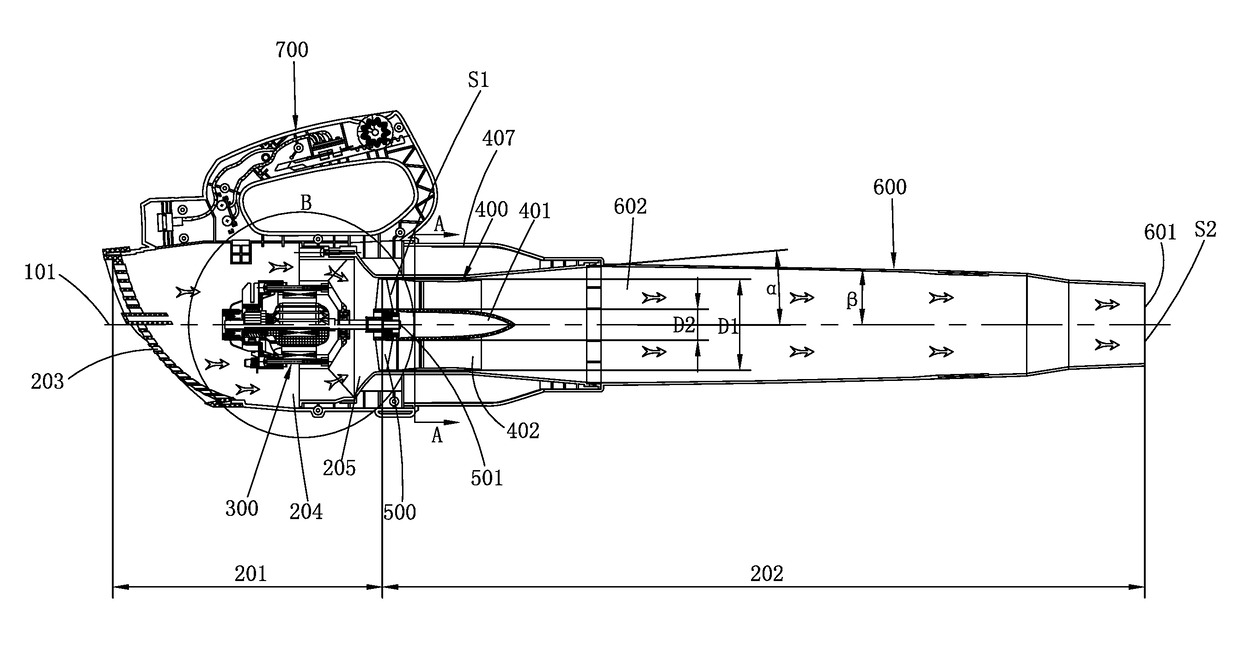
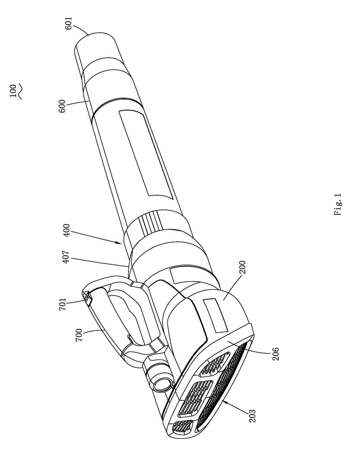
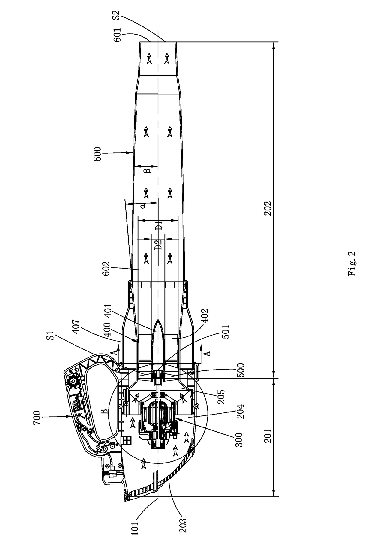
[0074]FIG. 1 to FIG. 11 illustrate a blower 100 according to a first embodiment of the present invention. The blower 100 includes a housing 200, a motor 300, a duct 400, a fan 500 and a blowing tube 600. The motor 300, the duct 400 and the fan 500 are all disposed in the housing 200. The blowing tube 600 is coupled to the housing 200.

[0075]As shown in FIG. 2 and FIG. 3, the blowing tube 600 and the housing 200 are coupled to form an air passage 602. The blowing tube 600 is provided thereon with an air outlet 601, and the air moves from the air passage 602 to the air outlet 601 and exits out of the air outlet 601, used for blowing away leaves and garbage on the ground. The ...


PUM


Abstract

A blower, comprising: a housing comprising an air inlet, a motor disposed in the housing, an axial fan configured to be driven to rotate about a fan axis and generate an air flow by the motor, a blowing tube configured to be coupled to the housing and comprising an air outlet, a duct configured to guide the air flow to the air outlet, the housing and the blowing tube comprises an air passage which comprises an upstream region between the inlet and the axial fan and a downstream region between the axial fan and the air outlet, the motor is disposed in the upstream region and the duct is disposed in the downstream region.

Description

BACKGROUND OF THE INVENTION[0001]In daily life, a blower is a common tool, usually used to clean up gardens, streets and other grounds.[0002]For example, U.S. Pat. No. 4,880,364 discloses a blower, including a housing, a motor, a fan and an air duct. The fan rotates to generate air flow that exits out of the air duct. However, the fan of such a blower uses a centrifugal fan, an inlet is disposed in a direction along a rotation axis of the centrifugal fan and an outlet is disposed in a radial direction of the centrifugal fan. Owing to the limitation of the structure of the centrifugal fan per se, the volume of air exiting is often not great, and thus the blowing effect is not good, which cannot well meet users' demands.[0003]For example, U.S. Pat. No. 5,975,862 discloses a blower that uses an engine as power, wherein the engine uses gasoline as fuel to serve as power, and the fan is still a centrifugal fan. However, as the power of the engine is greater than that of the general motor...

Claims


Application Information

Patent Timeline
Patent Type & Authority Applications(United States)
IPC IPC(8): F04D19/00F04D29/52F04D29/54F04D25/06F04D29/32
CPCF04D19/005F04D25/06F04D29/522F04D29/545F04D29/325A01G20/47E01H1/0809F04D19/002F04D25/084F04D29/326
Inventor GAO, ZHENDONGCESTONRO, ANDREAZHA, XIAHONGZHAO, FENGLIHUO, LIXIANGYU, XUEFENGSONG, KANGMA, ZHANHU
Owner POSITEC POWER TOOLS (SUZHOU) CO LTD
Why Eureka
Try Eureka