Autonomous driving control system for vehicle
a technology of autonomous driving and control system, which is applied in the direction of vehicle position/course/altitude control, process and machine control, etc., can solve the problems of low awakeness of the driver, liable to be maintained in an excessively tense state, and difficulty in suitably performing autonomous driving, etc., to accurately localize the host vehicle, low dependence of the output of the autonomous driving control part at this time, and high reliance on the output of the autonomous driving control par
- Summary
- Abstract
- Description
- Claims
- Application Information
AI Technical Summary
Benefits of technology
Problems solved by technology
Method used
Image
Examples
first embodiment
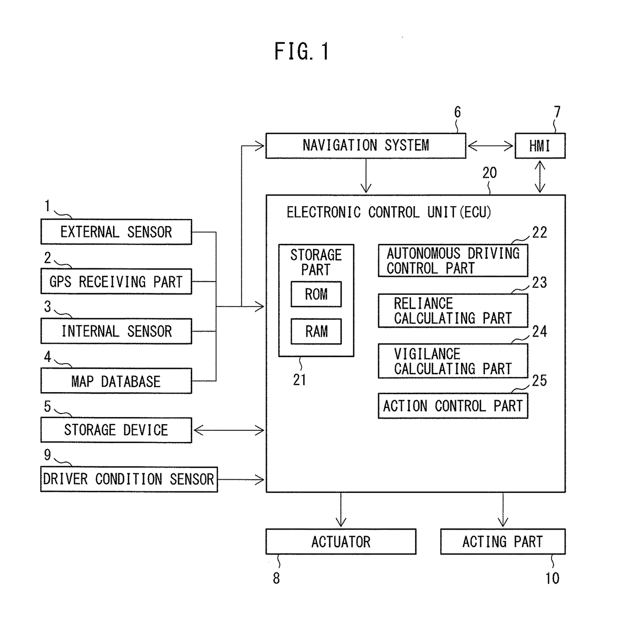
[0046]FIG. 1 shows a block diagram of an autonomous driving control system for a vehicle of a first embodiment according to the present invention. Referring to FIG. 1, the autonomous driving control system for a vehicle is provided with an external sensor 1, GPS receiving part 2, internal sensor 3, map database 4, storage device 5, navigation system 6, HMI (human machine interface) 7, actuator 8, driver condition sensor 9, acting part 10, and electronic control unit (ECU) 20.
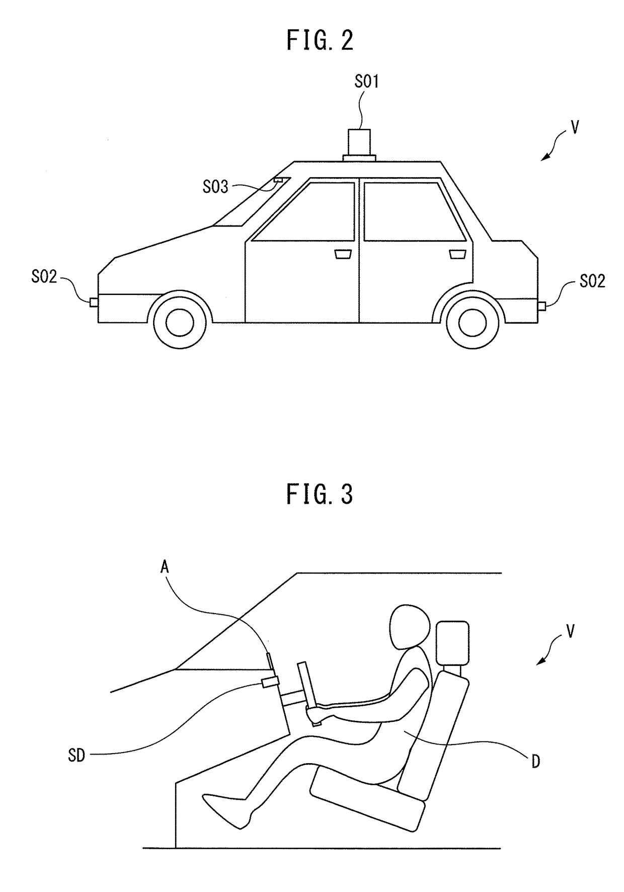
[0047]The external sensor 1 is a detection device for detecting information on an outside or surroundings of a host vehicle. The external sensor 1 is provided with at least one of a LIDAR (laser imaging detection and ranging), radar, and camera. In the first embodiment according to the present invention, as shown in FIG. 2, the external sensor 1 is provided with a LIDAR SO1, radar SO2, and camera S03.
[0048]The LIDAR SO1 is a device for detecting a road over which the host vehicle is running or at least one outsi...
second embodiment
[0116]FIG. 17 shows a block diagram of an autonomous driving control system for a vehicle of the second embodiment according to the present invention. Referring to FIG. 17, the electronic control unit 20 is further provided with a target vigilance calculating part 30 and vigilance deviation calculating part 31.
[0117]The target vigilance calculating part 30 is configured to calculate a lower limit target vigilance which is a lower limit target value of the driver vigilance, based on the autonomous driving output reliance. This lower limit target vigilance becomes lower as the autonomous driving output reliance becomes higher, as shown in FIG. 18. The lower limit target vigilance is stored in advance in the form of a map shown in FIG. 18 in the ROM of the storage part 21.
[0118]Referring again to FIG. 17, the vigilance deviation calculating part 31 is configured to calculate a vigilance deviation which is a deviation of the driver vigilance from the lower limit target vigilance. In the...
third embodiment
[0136]That is, the displayed autonomous driving output reliance 41r and the displayed driver vigilance 41v overlap if the driver vigilance is equal to or higher than the lower limit target vigilance, while the displayed autonomous driving output reliance 41r and the displayed driver vigilance 41v do not overlap if the driver vigilance is lower than the lower limit target vigilance. Therefore, if displaying the autonomous driving output reliance and driver vigilance in a side-by-side manner as in the third embodiment according to the present invention, the driver can easily recognize if the driver vigilance is equal to or higher than the lower limit target vigilance. For this reason, if the displayed autonomous driving output reliance 41r and the displayed driver vigilance 41v do not overlap, it is possible for the driver to increase the driver vigilance so that they overlap.
[0137]Note that, FIG. 27 shows a case where the autonomous driving output reliance is lower than the case show...
PUM
 Abstract
Description
Claims
Application Information
 - R&D
- Intellectual Property
- Life Sciences
- Materials
- Tech Scout
- Unparalleled Data Quality
- Higher Quality Content
- 60% Fewer Hallucinations
Browse by: Latest US Patents, China's latest patents, Technical Efficacy Thesaurus, Application Domain, Technology Topic, Popular Technical Reports.
© 2025 PatSnap. All rights reserved.Legal|Privacy policy|Modern Slavery Act Transparency Statement|Sitemap|About US| Contact US: help@patsnap.com


