
Solar access measurement

Active Publication Date: 2017-09-14
JOHN FLUKE MFG CO INC
View PDF3 Cites 52 Cited by
  • Summary
  • Abstract
  • Description
  • Claims
  • Application Information

AI Technical Summary

Benefits of technology

The patent describes a method for determining what amount of solar radiation will hit a specific location on the earth at a certain time. This is important for predicting the performance of solar power plants and other solar energy systems. The method involves creating two-dimensional matrices that include information about the light rays from the location to different positions in the sky. These matrices also include information about the amount of solar radiation that will be obstructed by clouds or other obstacles. By using these matrices, researchers can better predict the amount of sunlight that will be available for use at different locations on the planet. This technology helps to improve the efficiency and reliability of solar energy systems.

Problems solved by technology

These obstructions may be buildings, trees, vegetation, structures, or any other object that is in view from the desired site of the solar energy system.

Method used


Image

  • Solar access measurement
  • Solar access measurement
  • Solar access measurement

Examples


Embodiment Construction

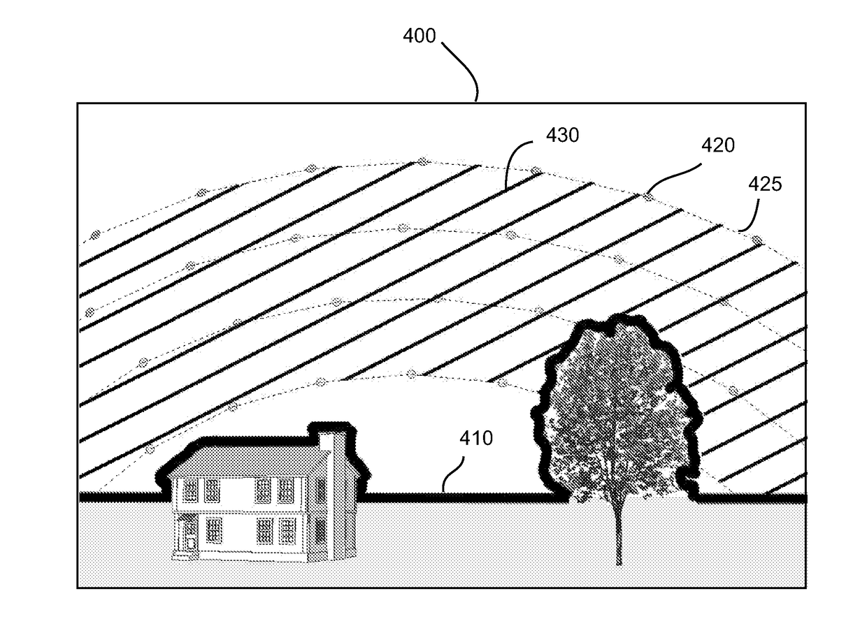
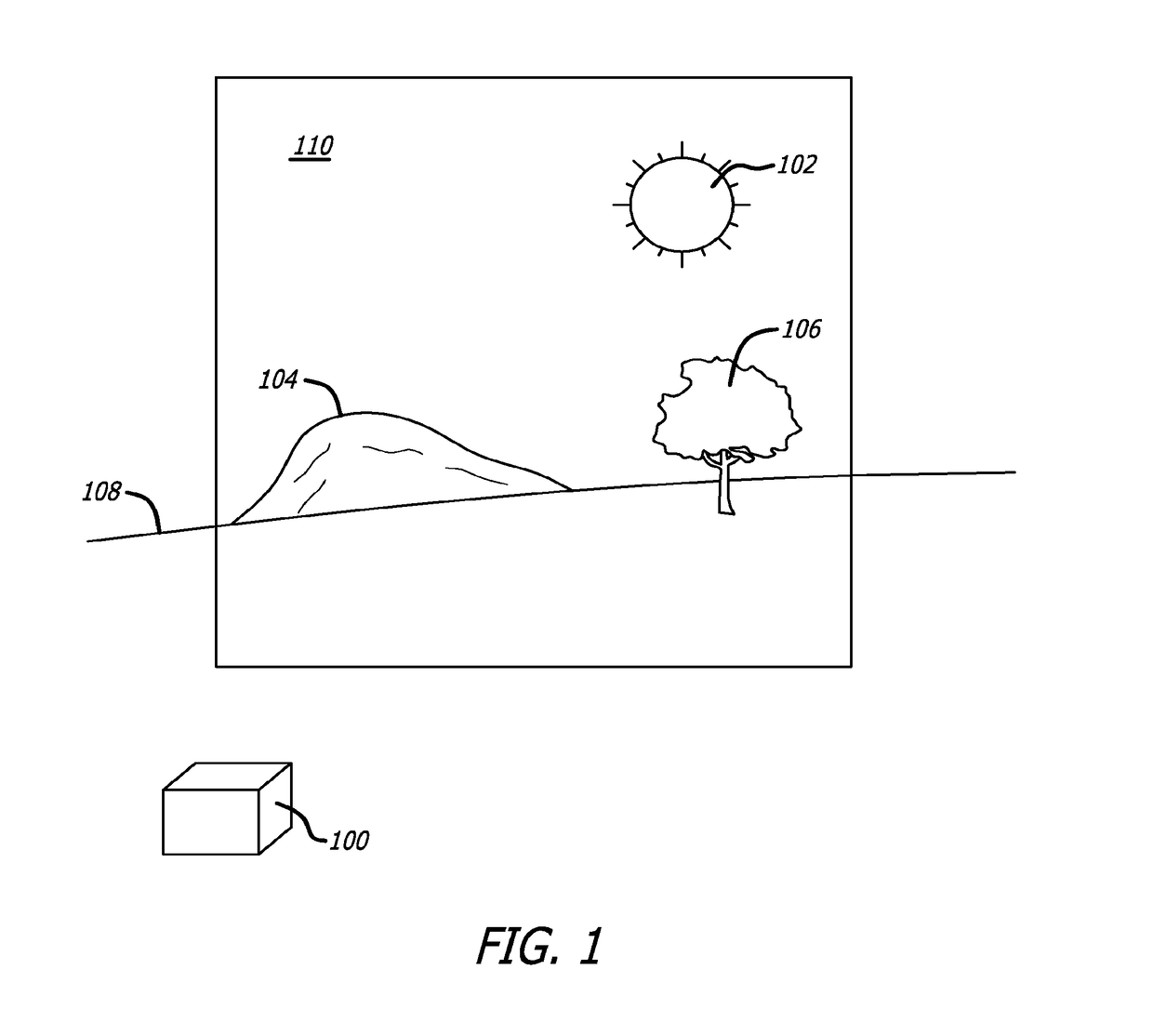
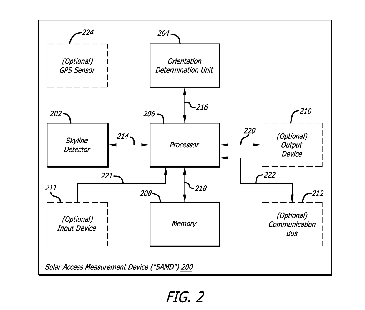
[0029]In the following description of the preferred embodiment, reference is made to the accompanying drawings that form a part hereof, and which show, by way of illustration, a specific embodiment in which the invention may be practiced. Other embodiments may be utilized and structural changes may be made without departing from the scope of the present invention.

[0030]A Solar Access Measurement Device (“SAMD”) is disclosed. The SAMD may be utilized as a “solar mapper” that is useful in the design and installation of solar energy systems, for example on a customer's roof or property, and a variety of other situations where solar radiation exposure needs to be measured, such as landscaping, architecture, ecological studies, fisheries, forestry, golf course management, realtors / appraisers, universities / technical schools, utility companies, etc. In general operation, the SAMD is positioned within a 3D CAD model and may capture a digital image with a virtual image sensor equipped with a...


PUM


Abstract

A method of determining solar radiation exposure at a predetermined location is provided. The method may include generating a first two-dimensional (2D) matrix including a plurality of elements, wherein each element of the plurality of elements of the first 2D matrix includes an elevation / azimuth pair representing a light ray extending from the predetermined location to one or more positions in the sky. The method may further include generating a second 2D matrix including a plurality of elements, wherein each index of the second 2D matrix includes an associated elevation / azimuth pair of the first 2D matrix. Each element of the plurality of elements of the second 2D matrix represents an amount of solar radiation to impinge on the predetermined location from a direction of a respective elevation / azimuth pair.

Description

CROSS REFERENCE TO RELATED APPLICATIONS[0001]This application is a continuation (CON) of U.S. Ser. No. 14 / 197,210, filed Mar. 4, 2014, which is a continuation in part (CIP) of U.S. Ser. No. 13 / 733,867, filed Jan. 3, 2013; which is a continuation (CON) of U.S. Ser. No. 12 / 952,101, filed Nov. 22, 2010, issued as U.S. Pat. No. 8,386,179; which is a continuation (CON) of U.S. Ser. No. 11 / 321,294, filed Dec. 28, 2005, issued as U.S. Pat. No. 7,873,490; and further claims benefit of priority with commonly owned U.S. Provisional Ser. No. 61 / 772,497, filed Mar. 4, 2013; the contents of each of which are hereby incorporated by reference.BACKGROUND OF THE INVENTION[0002]Field of the Invention[0003]This invention relates to solar measurement equipment, and in particular to measurement equipment capable of measuring solar access.[0004]Related Art[0005]With the advent of the modern industrialized society, there is a constant need for energy to power the growing energy consumption needs of the so...

Claims


Application Information

Patent Timeline
Patent Type & Authority Applications(United States)
IPC IPC(8): G06T17/05G01W1/12G01J1/42G01J1/02G01S3/786
CPCG01S3/7868G01W1/12G01J1/4228G01J1/0266G06T17/05Y02B10/10
Inventor MACDONALD, WILLARD S.MACDONALD, ROBERT
Owner JOHN FLUKE MFG CO INC
Learn More