
Fuse Cutout Monitoring and Indication Device

a monitoring device and fuse technology, applied in the direction of hot sticks switches, instruments, wireless communication, etc., can solve the problems of transformer being disconnected from the line, wasting a lot of time on searching for and wasting a lot of time on discovering a fuse tube that is detached

Active Publication Date: 2017-09-14
IOT SENSOR CORP
View PDF18 Cites 6 Cited by
  • Summary
  • Abstract
  • Description
  • Claims
  • Application Information

AI Technical Summary

Benefits of technology

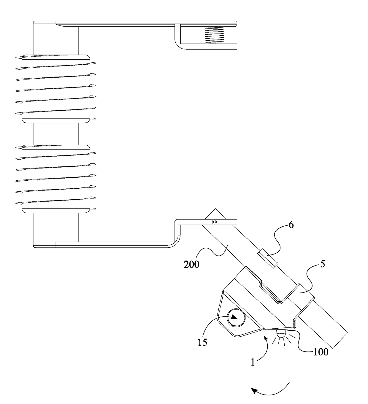
The present invention is a fuse cutout monitoring and indication device that can be used on a power distribution system with fuse cutouts. The device detects when the fuse cutout has detached from the fuse tube and alerts the authorities with a visual indicator. The device is designed as a retrofit that can be easily attached to existing fuse cutouts without needing to disconnect the electrical power supply. The technical effect of the invention is to provide a quick and efficient way to detect when a fuse cutout has detached and alert the authorities, allowing for quicker repairs and improved safety in the power distribution system.

Problems solved by technology

When an overcurrent is caused by a fault in the transformer or the customer circuit, the fuse melts within the fuse tube.
The melting results in the transformer being disconnected from the line.
Searching for a detached fuse tube can be extremely time consuming especially during low light conditions.
The amount of time spent on discovering the detached fuse tube can be disadvantageous when the power distribution system needs to be repaired within a short time.
The inability to be used with any existing fuse cutout can be financially disadvantageous since the fuse cutout needs to be redesigned to accommodate the fuse cutout monitoring device.

Method used


Image

  • Fuse Cutout Monitoring and Indication Device
  • Fuse Cutout Monitoring and Indication Device
  • Fuse Cutout Monitoring and Indication Device

Examples


Embodiment Construction

[0017]All illustrations of the drawings are for the purpose of describing selected versions of the present invention and are not intended to limit the scope of the present invention.

[0018]The present invention introduces a fuse cutout monitoring and indication device. More specifically, the present invention is a device that detects the detachment of a fuse tube from the attachment hooks of a fuse cutout and therefore is in a dropped position. When the detachment is detected, the present invention provides a visual alert or other comparable alert so that the location of the detached fuse tube can be found promptly. To do so, the present invention is designed as a retrofit that can be attached to the fuse tube of a fuse cutout.

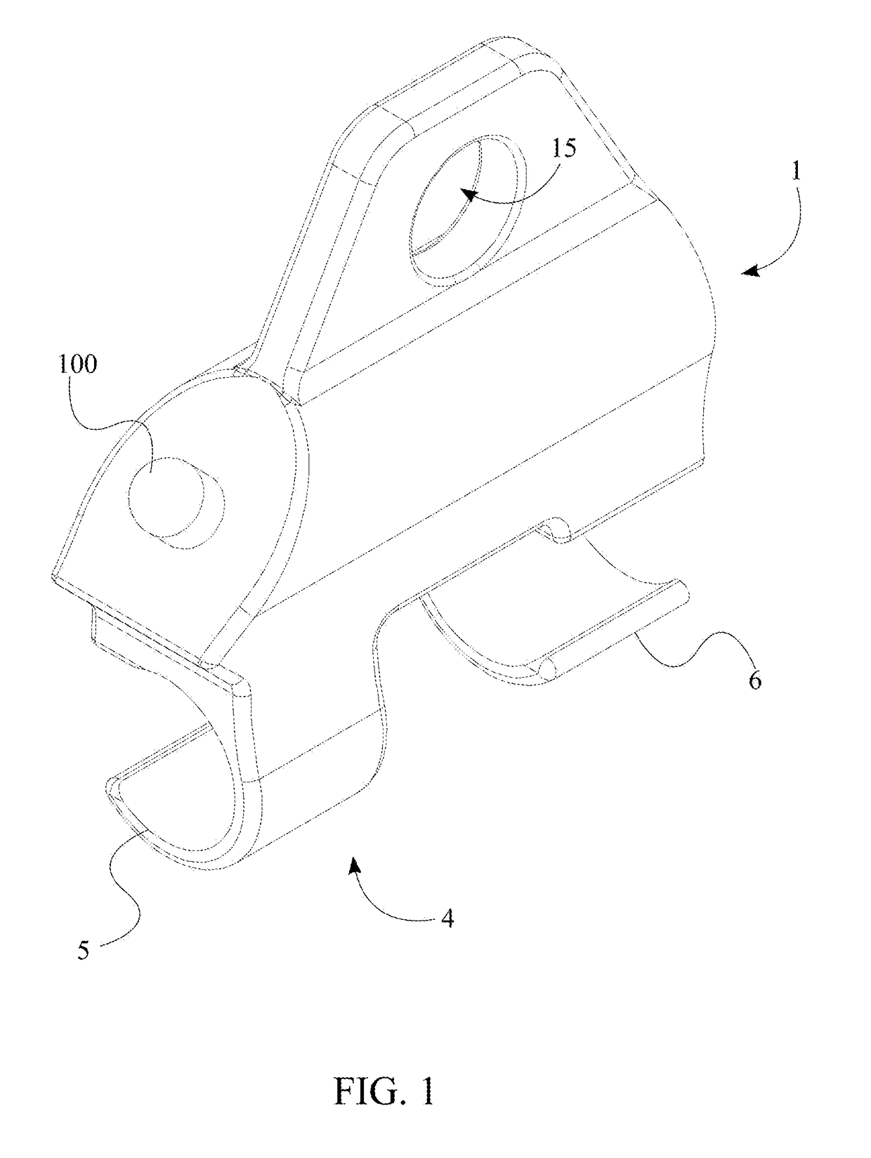
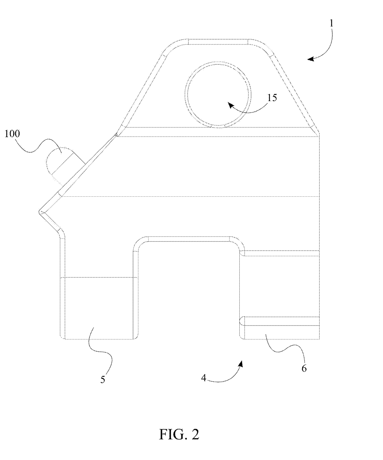
[0019]As illustrated in FIGS. 1-3 and FIG. 6, the present invention comprises a structural body 1, a tilt switch 2, a power source 3, a visual indicator 100, and an attachment mechanism 4. The structural body 1 gives the overall size and shape of the invention ...


PUM


Abstract

A device for monitoring and indicating a fuse tube detachment from a fuse cutout assembly contains a structural body, a tilt switch, a power source, a visual indicator, and an attachment mechanism. The attachment mechanism is used to mount the device onto the fuse tube. The tilt switch monitors the position of the fuse tube. More specifically, when the vertical position of the fuse tube changes to the dropped position the tilt switch is triggered. Thus, the visual indicator is illuminated. The illumination aids in the process of discovering the detached fuse tube. In addition to the visual indicator, the device can also be equipped with a wireless communication device and an alarm system. The wireless communication device can be used to provide the exact location of the detached fuse tube. On the other hand, the alarm system can be used to expedite the process of discovering the detached fuse tube.

Description

[0001]The current application claims a priority to the U.S. Provisional Patent application Ser. No. 62 / 307,751 filed on Mar. 14, 2016.FIELD OF THE INVENTION[0002]The present invention relates generally to safety equipment in the field of power systems. More specifically, the present invention is a fuse cutout monitoring device that is to be used on an electric power distribution system.BACKGROUND OF THE INVENTION[0003]In power distribution systems, a fuse cutout is a combination of a fuse and a switch. The fuse cutout is used in primary overhead lines. As an example, one use of the existing fuse cutouts is to protect distribution transformers from current surges and overloads. When an overcurrent is caused by a fault in the transformer or the customer circuit, the fuse melts within the fuse tube. The melting results in the transformer being disconnected from the line. The detachment from the line is executed by detaching a fuse tube of the fuse cutout assembly.[0004]With existing fu...

Claims


Application Information

Patent Timeline
IPC IPC(8): H01H85/02G01S19/14H01H35/02H01H85/32H01H85/175H01H36/00
CPCH01H85/0241H01H85/175H01H36/0006H01H35/02G08B5/36G01S19/14H01H2219/036H04W88/02H01H85/32H01H31/006H01H31/125H01H85/545
Inventor ROSENQUIST, CRAIG HAMILTON
Owner IOT SENSOR CORP
Learn More