Method and apparatus for determining the geographic location of a target

a geographic location and target technology, applied in image analysis, surveying and navigation, instruments, etc., can solve the problems of inability to perform additional mathematical transformations, inability to perform standard registration processes, and inability to collect information

Inactive Publication Date: 2004-03-04
LOCKHEED MARTIN CORP
View PDF0 Cites 47 Cited by
  • Summary
  • Abstract
  • Description
  • Claims
  • Application Information

AI Technical Summary

Benefits of technology

[0010] Therefore it is another object of the present invention to provide a method and apparatus for determining the exact location of a target depicted in a real-world image having a slant angle and focal plane location and orientation that are only approximately known using a virtual or synthetic environment representative of the real-world terrain where the target is generally located wherein a set of views of the virtual environment each having a known slant angles as well as focal plane orientation and location is compared with the real-world image to determine which simulated view most closely corresponds to the real-world view and then correlating the real-world image of the target with the selected simulated view to correctly locate the target in the virtual environment and thereby determine the exact geographic location of the target in the real-world.
[0011] These and other advantage objects and features of the present invention are achieved, according to one embodiment of the present invention, by an apparatus for determining the precise geographic location of a target located on a battlefield, the apparatus comprising: at least one information gathering asset having a sensor for generating a real-world image of the target on the battlefield, wherein the image has a slant angle and focal plane orientation and location that are only approximately known; means for removing lens or other distortions from the image; a communications system for conveying images from the information gathering asset to the apparatus; a computer having a display; a digital database having database data representative of the geography of the area of the world at the battlefield, wherein the computer accesses the digital database to transform said database data and create a virtual environment simulating the geography of battlefield that can be view in three-dimensions from any vantage point location and slant angle; means for generating a set of simulated views of the virtual environment, the set of simulated views being selected so as to include a simulated view having about the same slant angle and focal plan orientation and location as the real-world image; means for selecting the simulated view that most closely corresponds to the real-world image; and means for correlating the real-world image of target with the selected simulated view of the virtual environment to correctly locate the target in the virtual environment and thereby determine the exact geographic location of the target in the real-world.

Problems solved by technology

One of the disadvantages to the use of photography in intelligence work is the slowness of the information gathering process.
By the time that this process is completed the theatre of operation may have moved to an entirely different area and the intelligence, thus, becomes useless.
One particular difficulty encountered when using RPV imagery is that the slant angle of the image as well as the exact location and orientation of the real focal plane (A flat plane perpendicular to and intersecting with the optical axis at the on-axis focus, i.e., the transverse plane in the camera where the real image of a distant view is in focus.) of the camera capturing the image are only approximately known because of uncertainties in the RPV position (even in the presence of on-board GPS systems), as well as the uncertainties in the RPV pitch, roll, and yaw angles.
Generally, however, this standard registration process does not work without additional mathematical transformations for imagery having a non-zero slant angle because of differences in slant angles between the non-zero slant angle image and the vertical image.
Making the process even more difficult is the fact that the slant angle as well as the orientation and location of the focal plane of any image provided by an RPV can only be approximately known due to the uncertainties in the RPV position as noted above.
In such cases the image may contain insufficient data to allow correlation with any one of the set of simulated views of the virtual environment.

Method used


Image

  • Method and apparatus for determining the geographic location of a target
  • Method and apparatus for determining the geographic location of a target
  • Method and apparatus for determining the geographic location of a target

Examples


Embodiment Construction

)

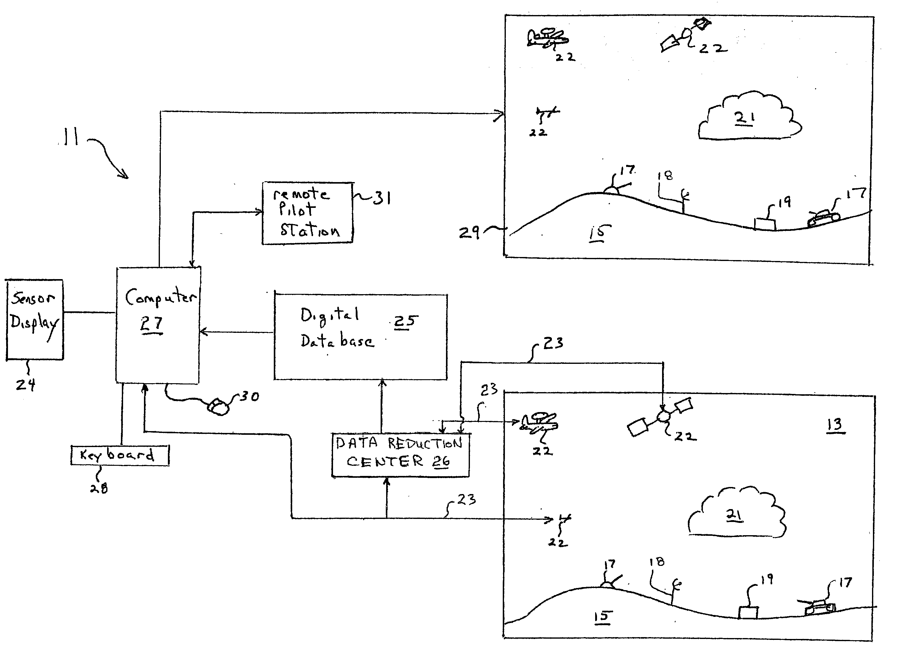
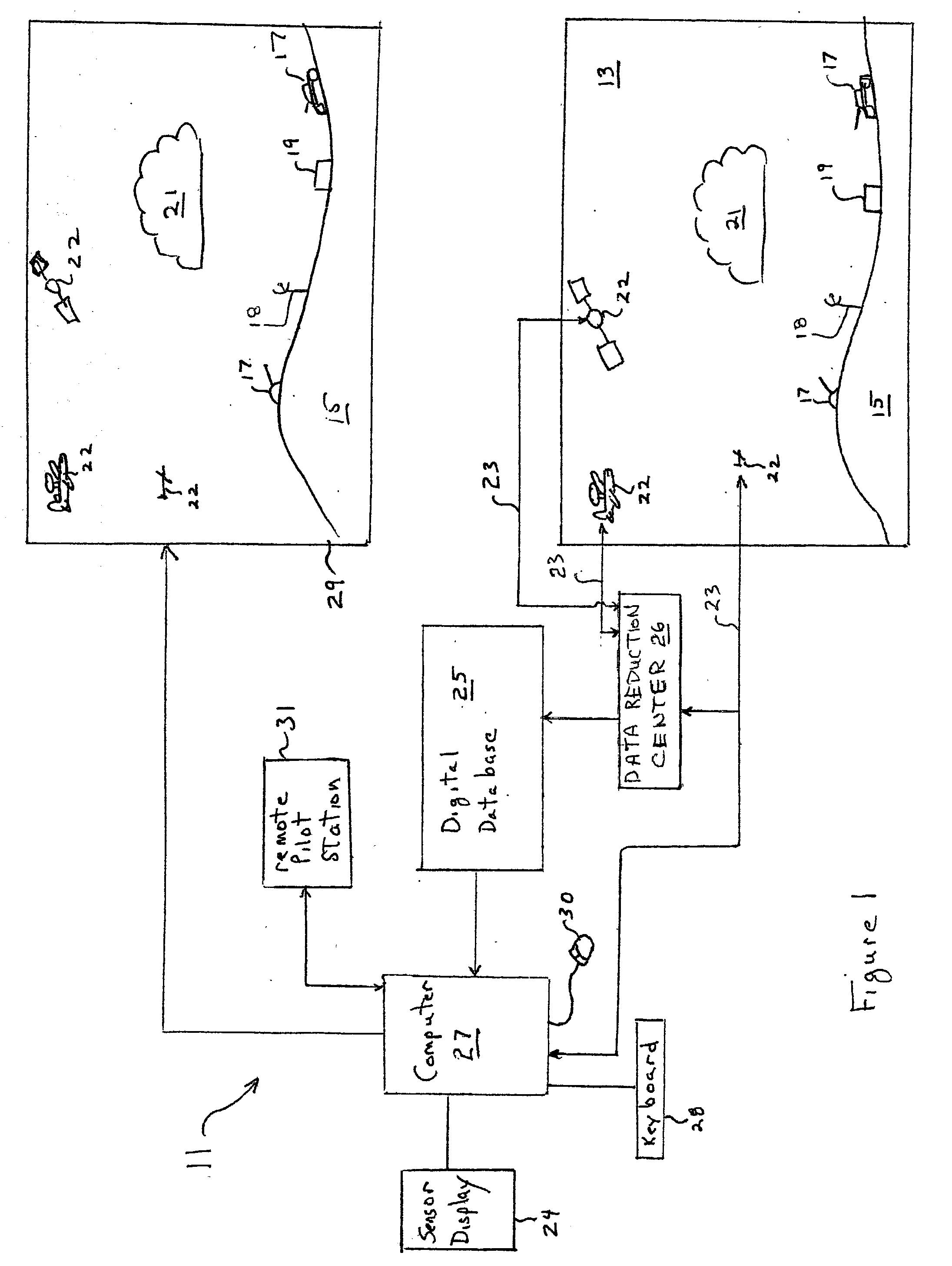
[0025] Referring to FIG. 1, a block diagram is provided that depicts the elements of one embodiment of an apparatus, generally indicated at 11, for determining the exact location of a target on a battlefield 13. As shown in FIG. 1, the battlefield has terrain 15, targets 17 at different locations, man-made structures 19, electronic warfare assets 18 as well as atmospheric conditions 21, such as natural conditions like water vapor clouds, or man-made conditions such smoke or toxic gas-like clouds that may or may not be visible to the naked eye. The apparatus 11 includes at least one information gathering asset 22 having one or more sensors for gathering information from the battlefield 13 in real-time. The information gathering asset 22 comprises, for example, an AWAC or the like, a satellite, a Remotely Piloted Vehicle (RPV) as well as forward observers (not shown) and any other known arrangement for gathering information from a battlefield. The one or more sensors on the asset 22 ...


PUM


Abstract

This invention generally relates to a method and apparatus for locating a target depicted in a real-world image that has a slant angle and vantage point location that are only approximately known using a virtual or synthetic environment representative of the real-world terrain where the target is generally located; and more particularly, to such a method and apparatus wherein a set of views of the virtual environment is compared with the real-world image of the target location for matching the simulated view that most closely corresponds to the real-world view in order to correlate the real-world image of the target with the selected simulated view in order to correctly locate the target in the virtual environment and thereby determine the exact location of the target in the real-world

Description

[0001] 1. Field of the Invention[0002] This invention generally relates to a method and apparatus for locating a target depicted in a real-world image taken from an imaging device having a slant angle and focal plane orientation and location that are only approximately known; and more particularly, to such a method and apparatus using a virtual or synthetic environment representative of the real-world terrain where the target is generally located to generate a simulated view that closely corresponds to the real-world image in order to correlate the real-world image and synthetic environment view and hence to correctly locate the target in the virtual environment and thereby determine the exact location of the target in the real-world. 2. Background of the Invention[0003] Historically, photography has been used by military intelligence to provide a depiction of an existing battlefield situation, including weather conditions, ground troop deployment, fortifications, artillery emplacem...

Claims


Application Information

Patent Timeline
Patent Type & Authority Applications(United States)
IPC IPC(8): G06T7/00
CPCG06T7/0044G06T7/74
Inventor HOGAN, JOHN M.POLLAK, EYTAN
Owner LOCKHEED MARTIN CORP
Why Eureka
Try Eureka