
Method for calibrating a device for measuring tracks

a technology for measuring devices and tracks, applied in railway auxiliary equipment, transportation and packaging, roads, etc., can solve the problems of no ideal track, no transducer calibration, and often forming an obstruction in the tight curve of cables, so as to increase the functional reliability of the track tamping machine and save costs

Active Publication Date: 2017-09-21
HP3 REAL GMBH
View PDF25 Cites 6 Cited by
  • Summary
  • Abstract
  • Description
  • Claims
  • Application Information

AI Technical Summary

Benefits of technology

The invention is a calibration apparatus for track tamping machines. The main advantage of this invention is that it provides a simple and efficient way to calibrate the machine on a relatively flat track section without the need for a "zero track." This means that the calibration can be done quickly and accurately by the operator on site, without the need for a person to move onto the track. This also reduces the risk of hazards and saves time and money. The invention also increases the reliability of the track tamping machine and ensures the functionality of the whole measurement system.

Problems solved by technology

Since tamping units which are also necessary for compacting the track are situated in the vicinity of said measuring transducer, the cord often forms an obstruction in the tight curve.
This is necessary because inaccuracies occur as a result of the constructive design.
Such inaccuracies are the result of constructive mechanical tolerances, imprecise mounting, mechanical play, errors in the measuring train etc.
The problem is the zero calibration of the transducers.
There is no ideal track however.
A track contains longitudinal level errors, superelevation errors, twists, directional errors and track gauge errors.
Since the required calibration precisions lie beneath 1 mm, real tracks are inadequate for this purpose.
The loading by the track tamping machine can lead to unknown deflections of the rail and the track grid, which impairs the precision of the calibration.
The employed zero calibration methods are therefore expensive, time-consuming, relatively imprecise and can only be carried out by qualified specialised staff.
Verification of the measurement system on the open track by the machine operator is virtually impossible.

Method used


Image

  • Method for calibrating a device for measuring tracks
  • Method for calibrating a device for measuring tracks
  • Method for calibrating a device for measuring tracks

Examples


Embodiment Construction

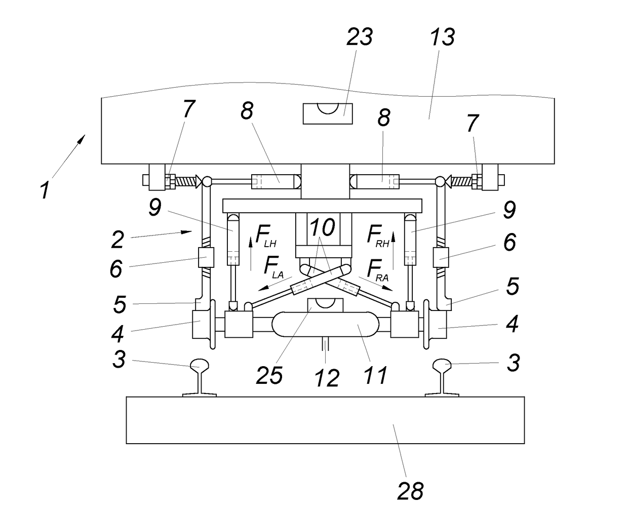
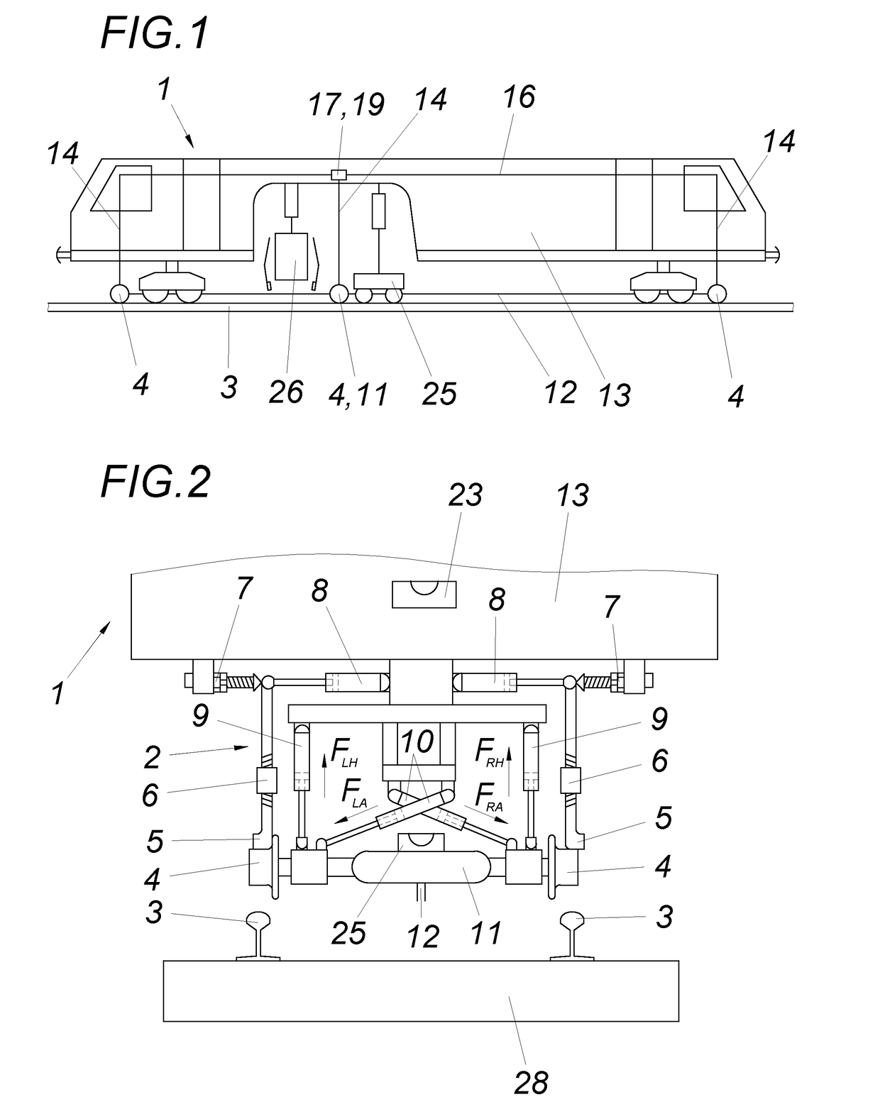
[0019]A track tamping machine 1 (FIG. 1) comprises a tamping unit 26 and a track lifting / lining unit 25. The machine frame 13 is used as a reference for absolute zero calibration. The lining unit consists of a lining steel cord 12, the three measuring cars 4 and a lining transducer 11. The levelling unit consists of two steel cords 16 which are tensioned over the rails, two levelling transducers 17 with steel cord acquisition sensors 19 and the levelling rods 14. The track tamping machine 1 travels on undercarriages on the rails 3.

[0020]Sensors for measuring the height position (levelling transducers 17), the direction (lining transducers 11), and the superelevation (inclinometers 25) are provided as track position measurement sensors for measuring the rails of a track (3, 28). The track-measuring car 4 is associated with a measuring-car lifting and lowering apparatus 9.

[0021]The machine frame 13 is associated with a calibration apparatus 2 with calibration stops 5, which can be mov...


PUM


Abstract

A method for calibrating a device for measuring tracks having a track-driveable track-measuring car with a lifting and lining device and track-position measurement sensors measuring the height, direction and superelevation of the rails of the track using the machine frame as a reference zero line. A lifting and lowering device is associated with the track-measuring car. A calibration device is associated with the machine frame the track-measuring car, for calibrating the sensors, is first lowered from a parking position, in which the track-measuring car is lifted from the track, onto the track or into an intermediate position. Calibration stops are moved by an actuator from an idle position into a calibration position, against which the track-measuring car is subsequently raised and applied. The values of the track-position measurement sensors are read out and stored in the measurement system as calibration values, and the track-measuring car is lowered onto the track.

Description

FIELD OF THE INVENTION[0001]The invention relates to a method for calibrating a device for measuring tracks, comprising at least one track-driveable track-measuring car associated with a lifting and lining device, and comprising track-position measurement sensors for measuring the height position, the direction and the superelevation of the rails of the track using the machine frame as a reference zero line, wherein a measuring-car lifting and lowering device is associated with the track-measuring car. A device for measuring tracks with a calibration device is further proposed.DESCRIPTION OF THE PRIOR ART[0002]Track tamping machines are machines for correcting the track position. Measuring systems are used for this purpose, which systems measure the actual track height position and the actual track direction position and the actual superelevation position of the track during work. The track grid is lifted and laterally aligned by means of a track lifting / track lining unit and fixed ...

Claims


Application Information

Patent Timeline
IPC IPC(8): E01B35/08E01B33/00B61K9/08
CPCE01B35/08E01B33/00B61K9/08E01B27/17E01B35/00G01C25/005B61K9/00
Inventor LICHTBERGER, BERNHARD
Owner HP3 REAL GMBH
Features
  • Generate Ideas
  • Intellectual Property
  • Life Sciences
  • Materials
  • Tech Scout
  • Unparalleled Data Quality
  • Higher Quality Content
  • 60% Fewer Hallucinations
Learn More