Method for the individual pitch control of rotor blades of a wind turbine, acceleration sensor for a rotor blade, rotor blade comprising an acceleration sensor, rotor blade of a wind turbine and wind turbine

a technology of rotor blades and sensors, applied in the direction of instruments, machines/engines, mechanical equipment, etc., can solve the problems of wind energy plants subject to a complex control, monitoring, and sensors required for monitoring subject to a multitude of constraints

Active Publication Date: 2017-09-21
VC VIII POLYTECH HLDG APS
View PDF5 Cites 15 Cited by
  • Summary
  • Abstract
  • Description
  • Claims
  • Application Information

AI Technical Summary

Benefits of technology

[0006]According to one embodiment, a method for the individual pitch control of rotor blades of a wind turbine is provided. The method comprises measuring an acceleration by means of an acceleration sensor in a rotor blade of a wind turbine; high-pass filtering a signal of the acceleration sensor in order to determine a time-variable parameter; and setting the pitch of the first rotor blade of the wind turbine using the time-variable parameter, said pitch setting being performed in the course of an individual pitch control.
[0007]According to one embodiment, a wind turbine is provided. The wind turbine comprises a first rotor blade that is mounted to a hub; a first drive unit for rotating the first rotor blade for a pitch control of the first rotor blade; at least one second rotor blade that is mounted to the hub; at least one second drive unit for rotating the second rotor blade for a pitch control of the second rotor blade, wherein the second drive unit is controllable independently of the first drive unit; a control unit for controlling at least the first drive unit; a first acceleration sensor in the first rotor blade of the wind turbine; means for high-pass filtering a signal of the first acceleration sensor for determining a time-variable parameter; and a control unit, with the control unit being configured to control a pitch setting of the first rotor blade using the time-variable parameter.

Problems solved by technology

Wind energy plants are subject to a complex control which may be required, for instance, by changing operating conditions.
Due to the conditions associated with the operation of a wind turbine, for example, temperature variations, atmospheric influences and weather conditions, yet also in particular strongly changing wind conditions, as well as the multitude of safety measures prescribed by law, the monitoring and the sensors required for the monitoring are subject to a multitude of constraints.

Method used


Image

  • Method for the individual pitch control of rotor blades of a wind turbine, acceleration sensor for a rotor blade, rotor blade comprising an acceleration sensor, rotor blade of a wind turbine and wind turbine
  • Method for the individual pitch control of rotor blades of a wind turbine, acceleration sensor for a rotor blade, rotor blade comprising an acceleration sensor, rotor blade of a wind turbine and wind turbine
  • Method for the individual pitch control of rotor blades of a wind turbine, acceleration sensor for a rotor blade, rotor blade comprising an acceleration sensor, rotor blade of a wind turbine and wind turbine

Examples


Embodiment Construction

[0027]Hereinafter, detailed reference is made to various embodiments of the invention, with one or more examples being illustrated in the drawings.

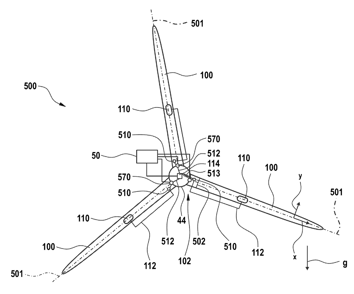
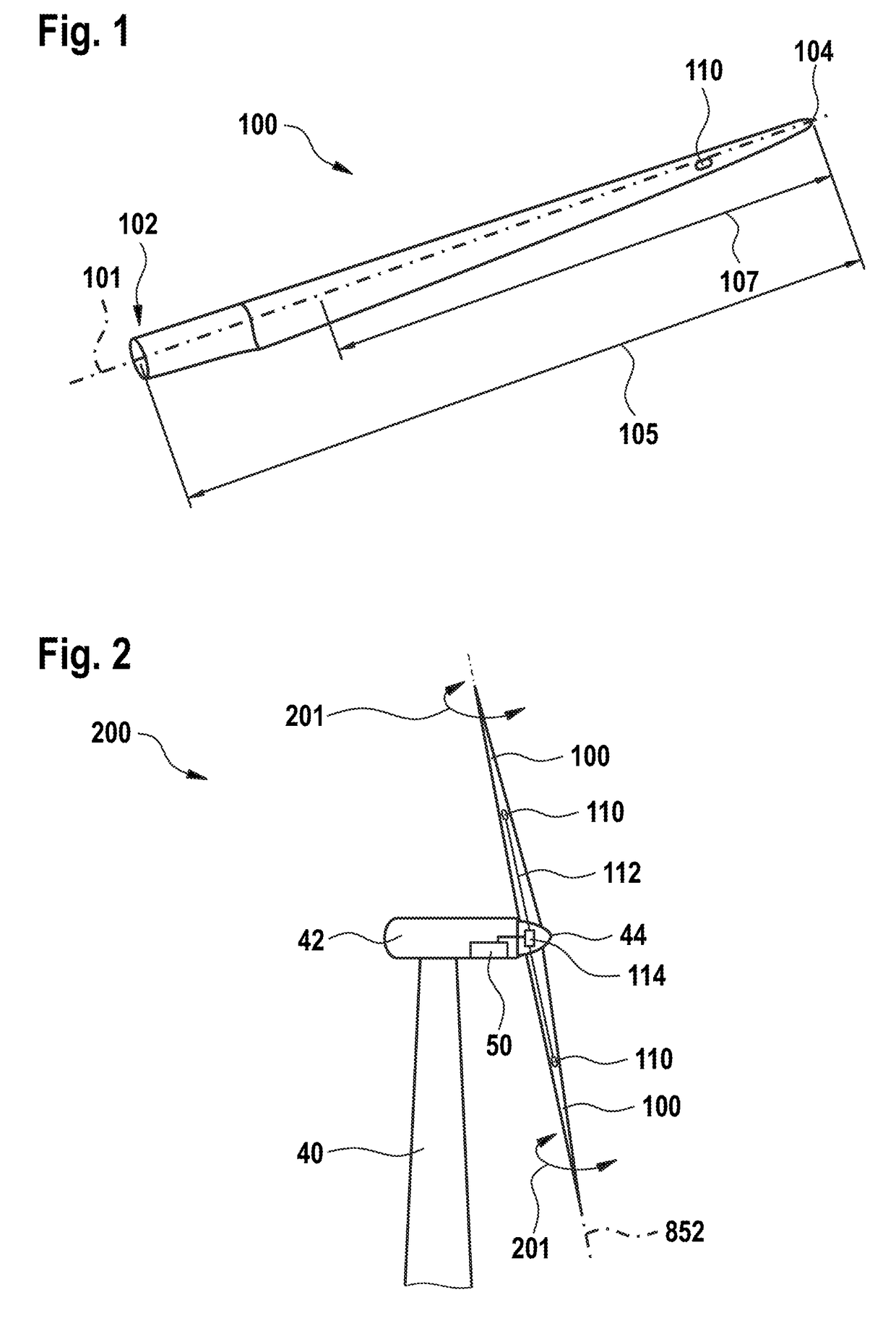
[0028]FIG. 1 shows a rotor blade 100 of a wind turbine. The rotor blade 100 has an axis 101 along its longitudinal extension. The rotor blade length 105 ranges from the blade flange 102 to the blade tip 104. According to embodiments described herein, an acceleration sensor 110 is located in an axial or radial area, i.e. in an area along the axis 101, with the acceleration sensor being provided at a radial position in the range of the outer 70% of the radius of a rotor blade of the wind turbine.

[0029]In practice so far, sensors have been attached close to the blade flange 102. Typically, sensors were in practice hitherto attached within the inner 20% of the radius of a rotor blade. This positioning hitherto has been a frequently required prerequisite since a stroke of lightning is a serious danger for wind energy plants or wind turbines. O...


PUM


Abstract

The invention relates to a method for the individual pitch control of the rotor blades of a wind turbine. The method comprises: measuring an acceleration by means of an acceleration sensor in a rotor blade of the wind turbine; high-pass filtering of a signal of the acceleration sensor in order to determine a time-variant variable; and setting the pitch of the first rotor blade of the wind turbine using the time-variant variable, said pitch setting being part of an individual pitch control.

Description

TECHNICAL FIELD[0001]Embodiments of the present invention generally relate to controlling and / or regulating and monitoring, respectively, the operation of wind turbines and the components used for this purpose such as acceleration sensors and / or the corresponding components of a wind turbine. Embodiments relate in particular to a method for the individual pitch control of rotor blades of a wind turbine, a rotor of a wind turbine, and a wind turbine.PRIOR ART[0002]Wind energy plants are subject to a complex control which may be required, for instance, by changing operating conditions. Due to the conditions associated with the operation of a wind turbine, for example, temperature variations, atmospheric influences and weather conditions, yet also in particular strongly changing wind conditions, as well as the multitude of safety measures prescribed by law, the monitoring and the sensors required for the monitoring are subject to a multitude of constraints.[0003]As an example, it is no...

Claims


Application Information

Patent Timeline
Patent Type & Authority Applications(United States)
IPC IPC(8): F03D7/02G01P15/093F03D80/30F03D17/00F03D1/06
CPCF03D7/0224F03D17/00F03D1/06F05B2270/807G01P15/093F05B2270/804F03D80/30F03D7/024F03D7/042F05B2270/334F05B2270/704Y02E10/72F05B2260/80
Inventor MULLER, MATHIASSCHUBERT, MATTHIAS
Owner VC VIII POLYTECH HLDG APS
Why Eureka
Try Eureka