Stator for rotating electric machine
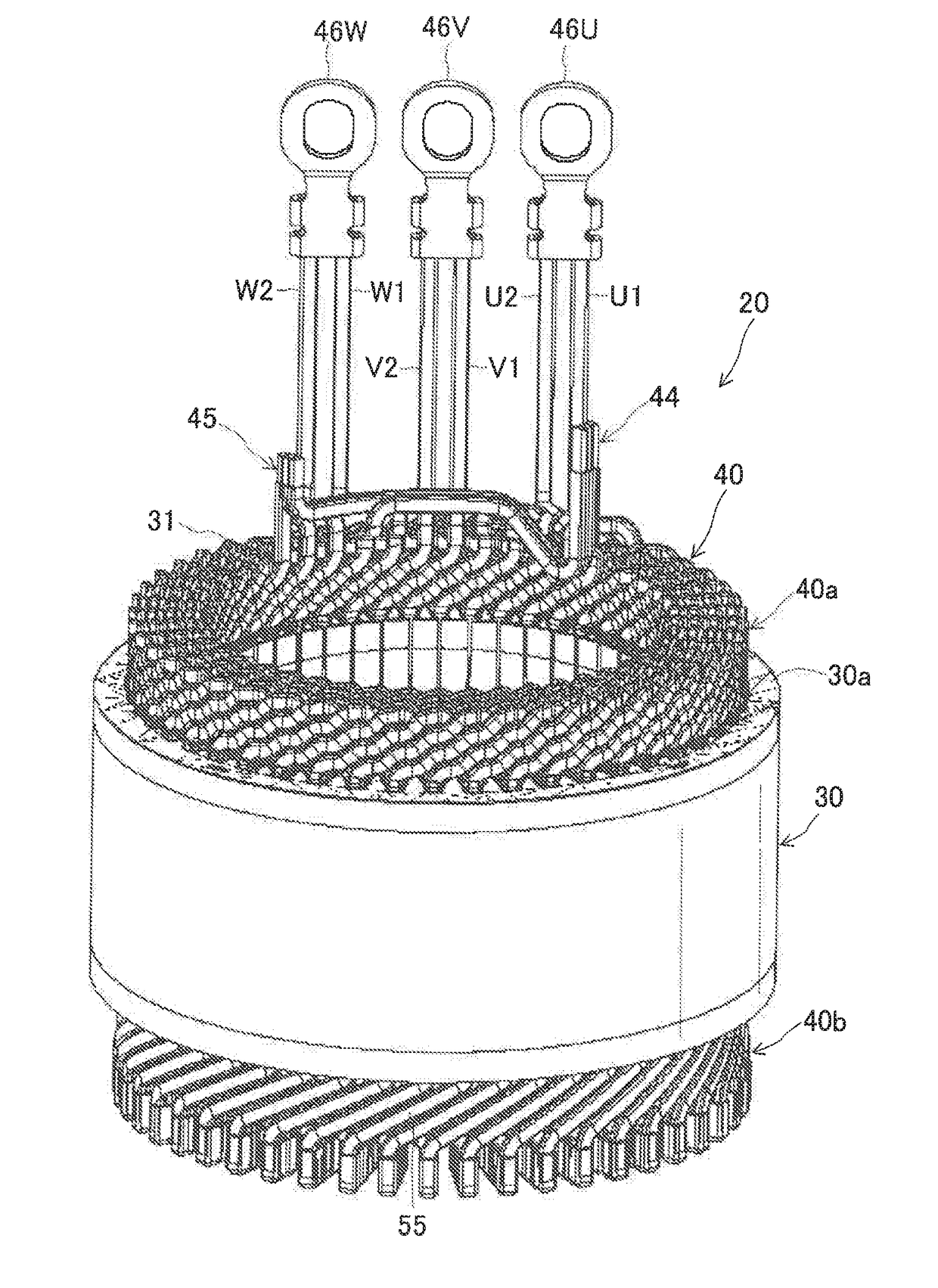
a technology of rotating electric machines and rotating shafts, which is applied in the direction of dynamo-electric machines, electrical apparatus, windings insulation materials, etc., can solve problems such as breakage or disconnection of joints, and achieve the effects of reducing stress in joints, reducing the length of lead wires, and reducing the weight of lead wires
- Summary
- Abstract
- Description
- Claims
- Application Information
AI Technical Summary
Benefits of technology
Problems solved by technology
Method used
Image
Examples
first embodiment
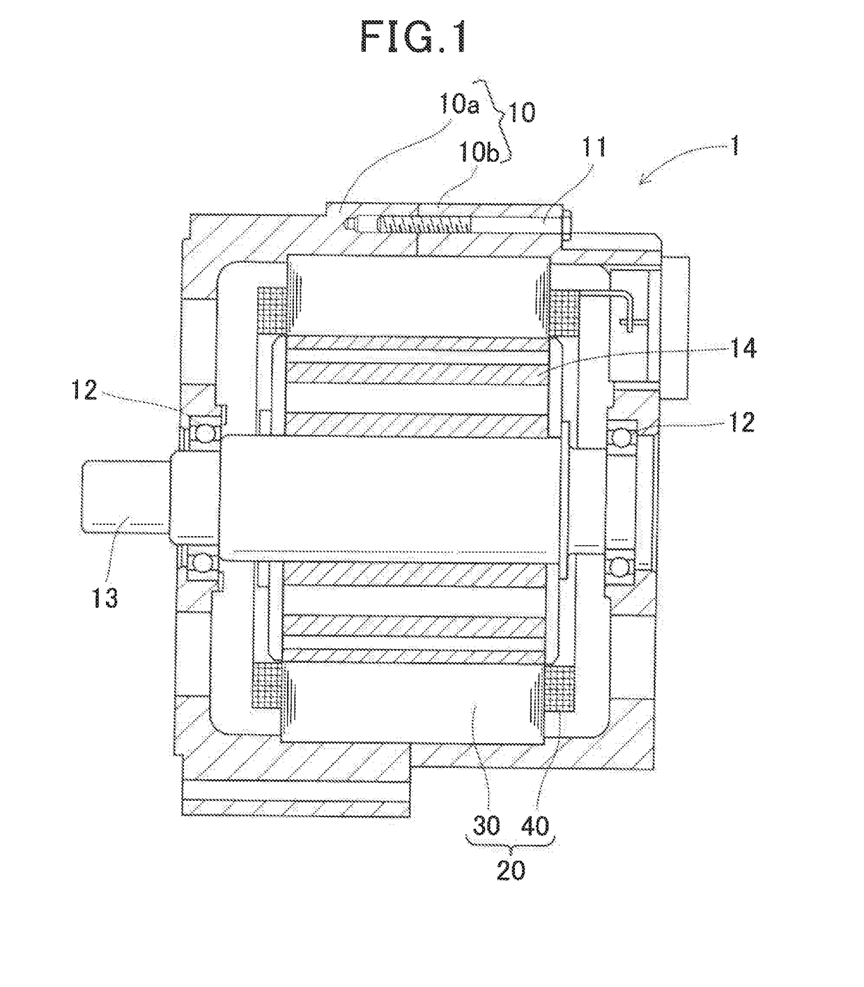
[0032]FIG. 1 shows the overall configuration of a rotating electric machine 1 which includes a stator 20 according to a first embodiment.
[0033]The rotating electric machine 1 is designed to be used in a motor vehicle, such as a passenger car or truck, as an electric motor.
[0034]As shown in FIG. 1, the rotating electric machine 1 further includes a housing 10, a rotating shaft 13 and a rotor 14 in addition to the stator 20.
[0035]The housing 10 has a substantially hollow cylindrical shape with both axial ends thereof closed. The housing 10 is comprised of a pair of cup-shaped housing pieces 10a and 10b. The housing pieces 10a and 10b are fastened, for example by bolts 11, into one piece with open ends thereof opposed to each other. The housing 10 has a pair of bearings 12 provided respectively in opposite axial end walls thereof.
[0036]The rotating shaft 13 is rotatably supported by the housing 10 via the pair of bearings 12.
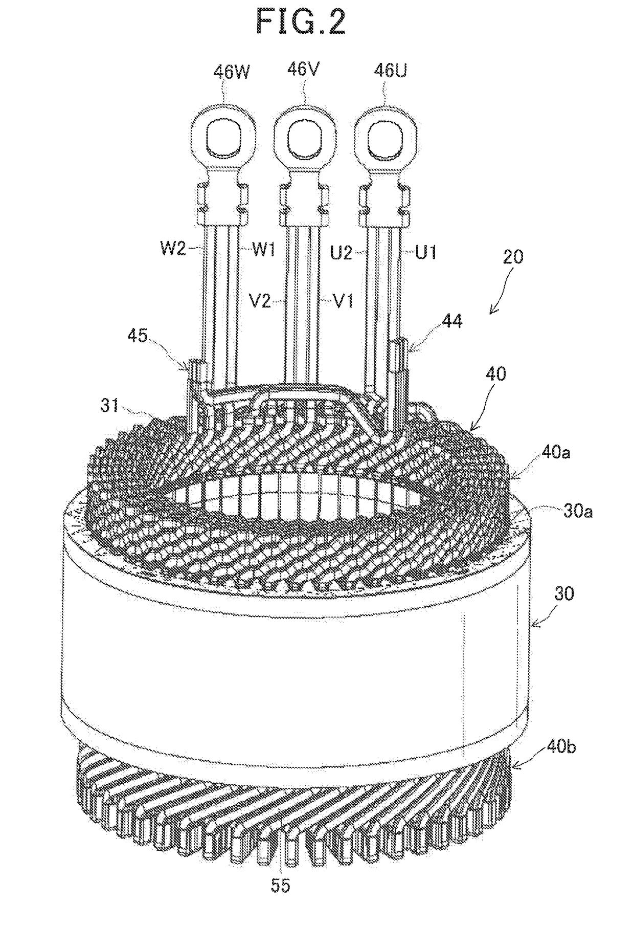
[0037]The rotor 14 is received in the housing 10. The rotor 1...
second embodiment
[0073]A stator 20 according to a second embodiment has almost the same structure as the stator 20 according to the first embodiment. Therefore, the differences of the stator 20 according to the second embodiment from the stator 20 according to the first embodiment will be mainly described hereinafter.
[0074]In the present embodiment, as shown in FIG. 8, the neutral lead wires of the first U-phase, V-phase and W-phase windings U1, V1 and W1 are arranged to extend axially outward from the axial end face 40d of the first coil end part 40a of the stator coil 40, so that the first joint 44, where the distal ends of the neutral lead wires of the windings U1, V1 and W1 are joined, is located at a position away from an inner surface of an axial end wall of the housing 10 by a predetermined distance.
[0075]Moreover, as shown in FIG. 9, an elastic member 48 is mounted on the first joint 44. The elastic member 48 includes a main body portion 48a and an elastic supporting portion 48b. The main bo...
third embodiment
[0079]A stator 20 according to a third embodiment has almost the same structure as the stator 20 according to the second embodiment. Therefore, the differences of the stator 20 according to the third embodiment from the stator 20 according to the second embodiment will be mainly described hereinafter.
[0080]In the present embodiment, as shown in FIG. 10, a temperature-sensing element 49 is arranged between the first joint 44 and the elastic member 48 mounted on the first joint 44. The temperature-sensing element 49 senses the temperature of the stator coil 40, which generates heat during operation of the rotating electric machine 1, at the first joint 44 and outputs a signal indicative of the sensed temperature to a not-shown controller. The controller detects failure (e.g., breakage or disconnection) of the first joint 44 by monitoring the temperature sensed by the temperature-sensing element 49.
[0081]On the other hand, no temperature-sensing element is arranged between the second j...
PUM
 Abstract
Description
Claims
Application Information
 - R&D
- Intellectual Property
- Life Sciences
- Materials
- Tech Scout
- Unparalleled Data Quality
- Higher Quality Content
- 60% Fewer Hallucinations
Browse by: Latest US Patents, China's latest patents, Technical Efficacy Thesaurus, Application Domain, Technology Topic, Popular Technical Reports.
© 2025 PatSnap. All rights reserved.Legal|Privacy policy|Modern Slavery Act Transparency Statement|Sitemap|About US| Contact US: help@patsnap.com


