Autostereoscopic display device and driving method

a display device and autostereoscopic technology, applied in the direction of 3d-image rendering, instruments, computing, etc., can solve the problems of spatial resolution at the expense of spatial resolution, and spatial resolution reduction at the expense of the problem of spatial resolution

Inactive Publication Date: 2017-09-21
KONINKLJIJKE PHILIPS NV
View PDF3 Cites 5 Cited by
  • Summary
  • Abstract
  • Description
  • Claims
  • Application Information

AI Technical Summary

Benefits of technology

[0048]The spatial and temporal multiplexing approaches outlined above can be combined, and various combinations of effects can then be generated. In particular, different combinations of spatial resolution, angular view resolution...

Problems solved by technology

This comes at the expense of the spatial resolution.
For example, content at zero depth may require a lower angular view resolution whereas content a...

Method used


Image

  • Autostereoscopic display device and driving method
  • Autostereoscopic display device and driving method
  • Autostereoscopic display device and driving method

Examples


Embodiment Construction

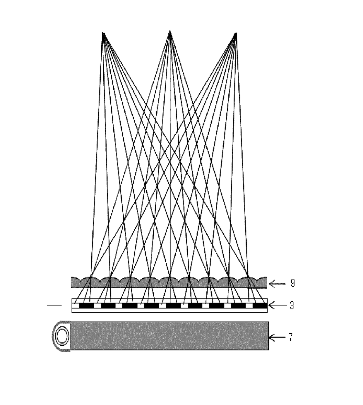
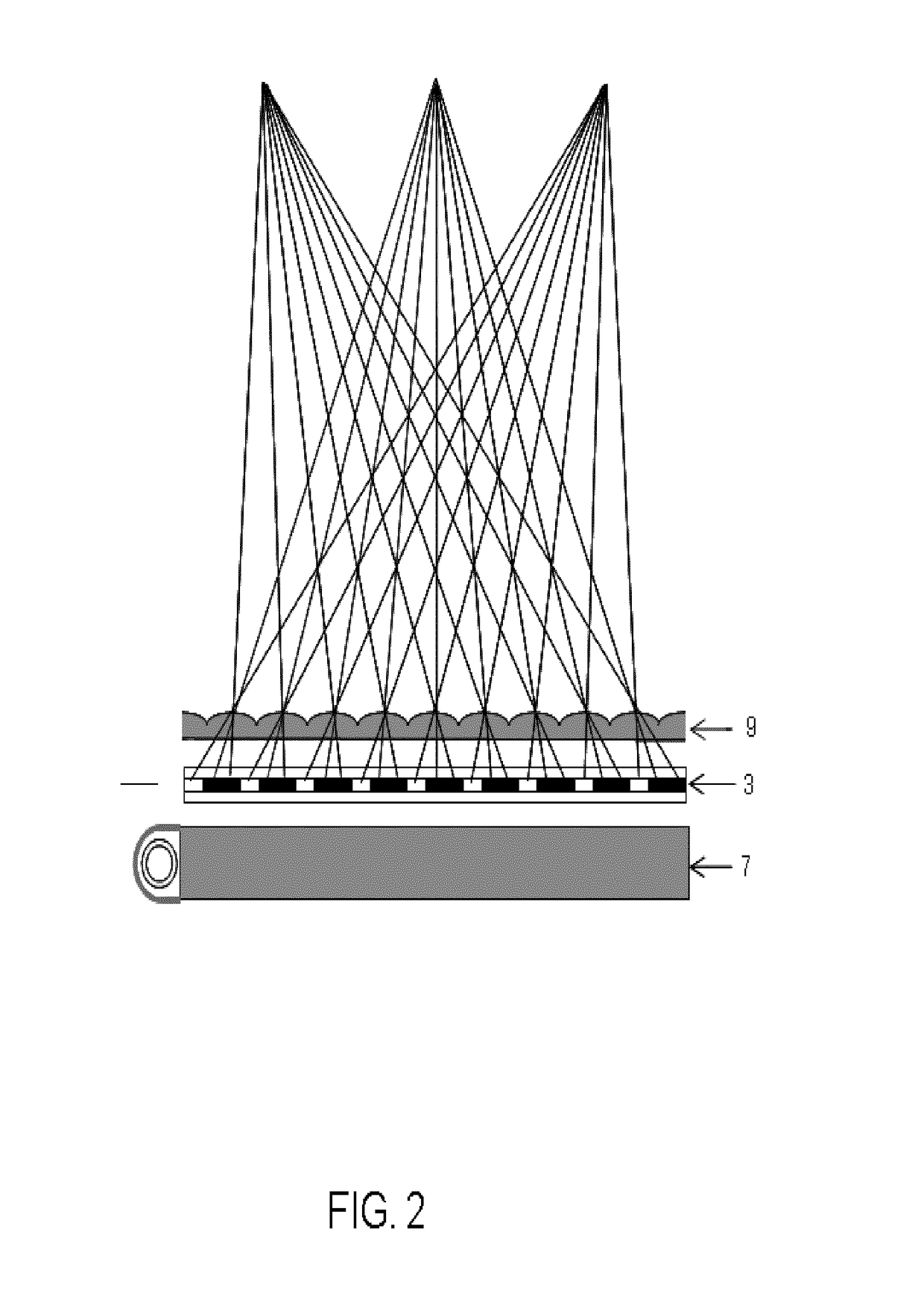
[0091]The invention provides an autostereoscopic display which uses a beam control system and a pixelated spatial light modulator. Different display modes are provided for the displayed image as a whole or for image portions. These different modes provide different relationships between angular view resolution, spatial resolution and temporal resolution. The different modes make use of different amounts of beam spread produced by the beam control system.

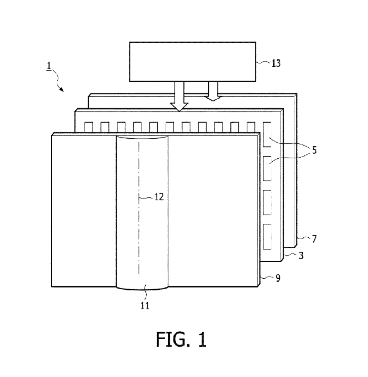
[0092]FIG. 5 shows a display device in accordance with an example of the invention. FIG. 5(a) shows the device and FIGS. 5(b) and 5(c) illustrate schematically two possible conceptual implementations.

[0093]The display comprises 30 a backlight for producing a collimated light output. The backlight should preferably be thin and low cost. Collimated backlights are known for various applications, for example for controlling the direction from which a view can be seen in gaze tracking applications, privacy panels and enhanced brightness p...


PUM


Abstract

An autostereoscopic display uses a beam control system and a pixelated spatial light modulator. Different display modes are provided for the displayed image as a whole or for image portions. These different modes provide different relationships between angular view resolution, spatial resolution and temporal resolution. The different modes make use of different amounts of beam spread produced by the beam control system.

Description

FIELD OF THE INVENTION[0001]This invention relates to an autostereoscopic display device and a driving method for such a display device.BACKGROUND OF THE INVENTION[0002]A known autostereoscopic display device comprises a two-dimensional liquid crystal display panel having a row and column array of display pixels (wherein a “pixel” typically comprises a set of “sub-pixels”, and a “sub-pixel” is the smallest individually addressable, single-colour, picture element) acting as an image forming means to produce a display. An array of elongated lenses extending parallel to one another overlies the display pixel array and acts as a view forming means. These are known as “lenticular lenses”. Outputs from the display pixels are projected through these lenticular lenses, which function to modify the directions of the outputs.[0003]The lenticular lenses are provided as a sheet of lens elements, each of which comprises an elongate partially-cylindrical (e.g. semi-cylindrical) lens element. The ...

Claims


Application Information

Patent Timeline
IPC IPC(8): H04N13/04G02B26/00G02B27/22G02B30/28G02B30/31H04N13/363
CPCH04N13/0497H04N13/0447H04N13/0404H04N13/0459G02B27/225G02B26/005H04N13/0422H04N13/0413H04N13/305G02F1/1323G02B30/26H04N13/363H04N13/315H04N13/324H04N13/351H04N13/398G02F1/294G02B30/28G02B30/31G06T15/00
Inventor KROON, BARTJOHNSON, MARK THOMAS
Owner KONINKLJIJKE PHILIPS NV
Why Eureka
Try Eureka