Eureka AIR delivers breakthrough ideas for toughest innovation challenges, trusted by R&D personnel around the world.

Amplifier circuit for improved sound

Active Publication Date: 2017-09-21
BLUEPRINT ACOUSTICS
View PDF6 Cites 0 Cited by
  • Summary
  • Abstract
  • Description
  • Claims
  • Application Information

AI Technical Summary

Benefits of technology

The present invention is about improving the sound quality of an amplifier with multiple output filters. It does this by using a bi-wiring principle that ensures the current flow through the output damping inductor is the same as the current flow into the loudspeaker driver. This results in improved sound quality without the need for additional amplifiers.

Problems solved by technology

In multi-band loudspeaker systems it is often observed that passive loudspeaker systems lack the sound quality of bi-amped or active loudspeaker systems.
However loudspeaker drivers in passive multi-band systems are not “firmly” connected to the low output impedance “controlled output” or feedback point of the amplifier.
However in consumer packaged amplifiers they rarely are firmly tied because damping output inductors and / or other components are typically present between the controlled output or feedback point and the amplifier terminals.
Typically in a passive system, the damping output inductor or equivalent circuitry in the amplifier and cable impedances isolate the controlled output or feedback point from a branching point to individual loudspeaker drivers so that back EMF from drivers results in circulating currents between drivers causing audible corruption of the sound produced.

Method used


Image

  • Amplifier circuit for improved sound
  • Amplifier circuit for improved sound
  • Amplifier circuit for improved sound

Examples


Embodiment Construction

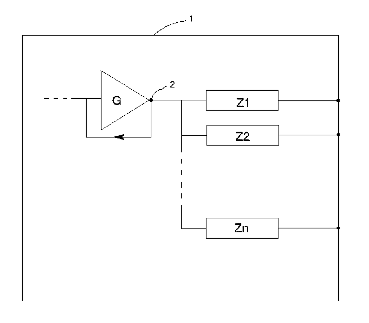
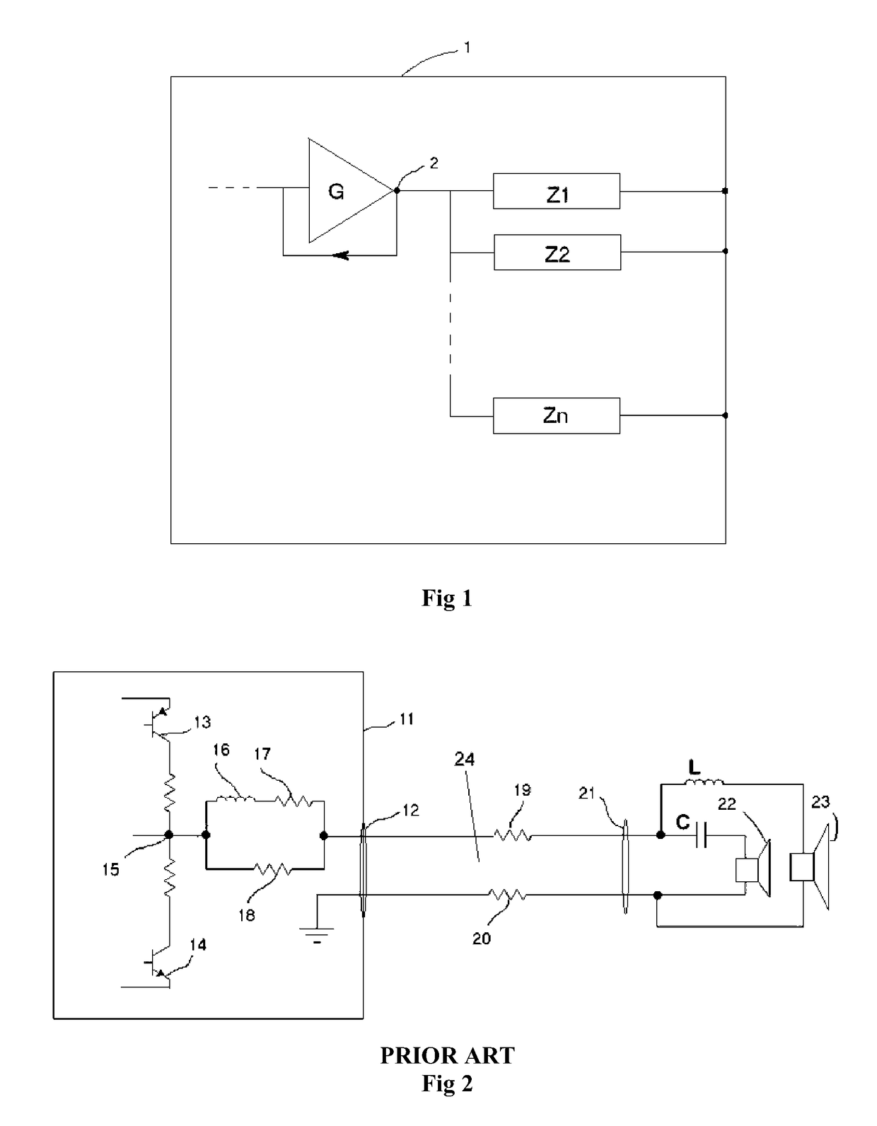
[0022]FIG. 1 shows an overview of the present invention in schematic form. Amplifier 1 contains an amplifier circuit G with feedback originating from feedback point 2. Output impedances Z1 to Zn, which may vary from each other, represent independent damping output inductors and include any other circuitry added to the output of amplifier G past feedback point 2 for feeding a load such as loudspeaker drivers 22, 23 as shown in FIG. 2, connected to amplifier G.

[0023]FIG. 2 shows an amplifier 11 in a common prior art configuration including connector 12 which may comprise a pair of binding posts or a connector socket. Internal to amplifier 11 is a pair of active output devices comprising bipolar devices 13, 14. Bipolar devices 13, 14 are exemplified for illustrative purposes only, but serve to identify the controlled output or feedback point 15 of amplifier 11 from which a feedback signal is typically taken. In the forward direction a damping output inductor is shown comprising an idea...


PUM


Abstract

An amplifier circuit is disclosed suitable for feeding a loudspeaker system having plural drivers. The amplifier circuit has an output stage and plural output connectors such that there is an output connector for each driver, wherein the output stage is connected separately to each output connector for independent connection to each driver. A method of feeding a loudspeaker system having plural drivers with an amplifier circuit having an output stage is also disclosed.

Description

TECHNICAL FIELD[0001]The present invention relates to an amplifier circuit suitable for audio applications and in particular relates to an amplifier circuit for improved sound quality.Definitions[0002]In this specification “amplifier” refers to a single audio power amplifier (i.e. one channel) and includes an electronic amplifier circuit and any peripheral apparatus associated with the amplifier in a consumer packaged form, including power supplies, protection devices, signal conditioning, switches, potentiometers, connectors and a case or enclosure. However it excludes other amplifier circuits that may be included in the same case or enclosure. Thus in the case of a stereo amplifier product, in this context there are two “amplifiers” to which the present invention may be applied.[0003]In this specification the “controlled output” of an amplifier denotes the final output amplification stage. Typically it is the point in an amplifier circuit where an output feedback loop commences. A...

Claims


Application Information

Patent Timeline
IPC IPC(8): H04R3/14H03F3/213H03F1/32H03F3/187
CPCH04R3/14H03F3/187H03F2200/03H03F1/32H03F3/213
Inventor VELICAN, ZELJKODOWER, WALTER MELVILLE
Owner BLUEPRINT ACOUSTICS
Why Eureka
Eureka Blog
Learn More