
Virtual base station apparatus and communication method

Active Publication Date: 2017-09-21
PANASONIC INTELLECTUAL PROPERTY CORP OF AMERICA
View PDF0 Cites 10 Cited by
  • Summary
  • Abstract
  • Description
  • Claims
  • Application Information

AI Technical Summary

Benefits of technology

The patent describes a way to improve a millimeter-wave network by increasing the area it covers and reducing the time required for beamforming training. This means that more people can be served and data can be transmitted faster. Overall, this enhances the efficiency of millimeter-wave networks and improves their overall performance.

Problems solved by technology

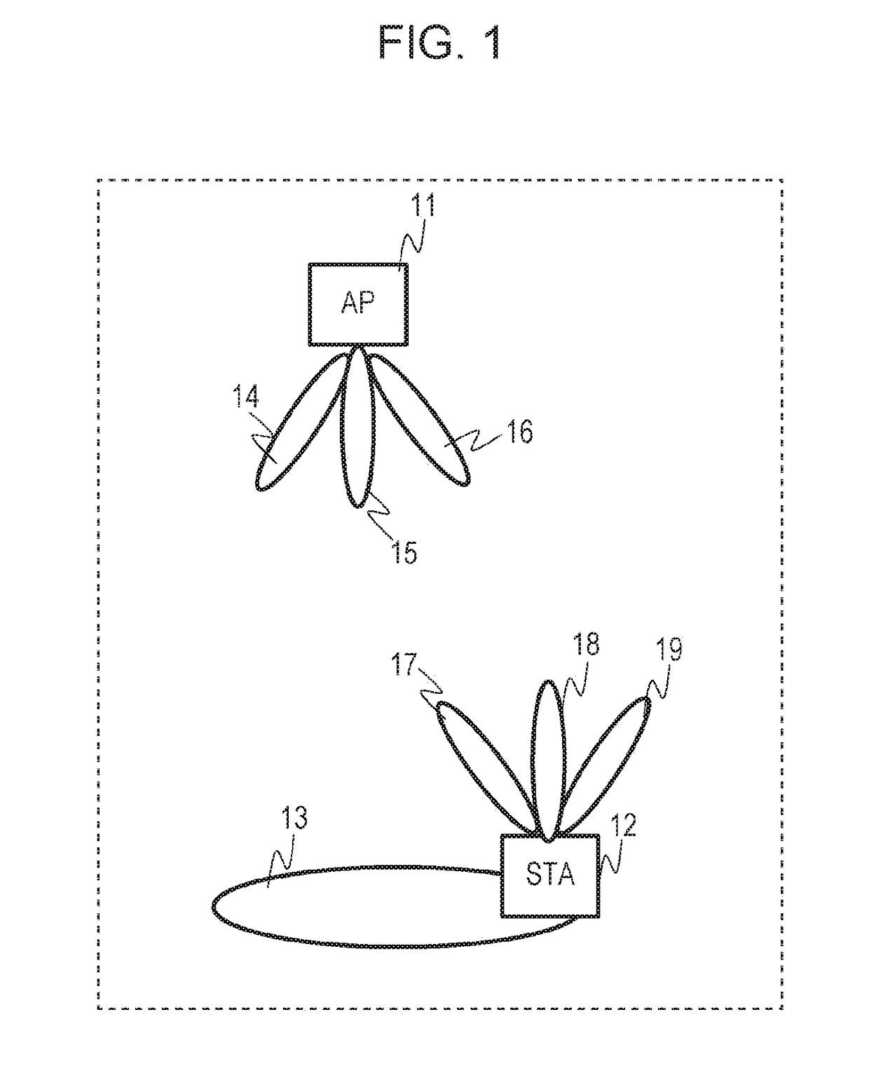
Communication using the millimeter wave bands causes propagation loss greater than that using the microwave bands, and it is difficult to extend the arrival range of radio waves.
In the beamforming training, the base station apparatus needs to have directivity (scan) over a wider angle to increase the cell area that is covered, and the time required for the beamforming training becomes overhead, resulting in a reduction in frequency use efficiency.

Method used


Image

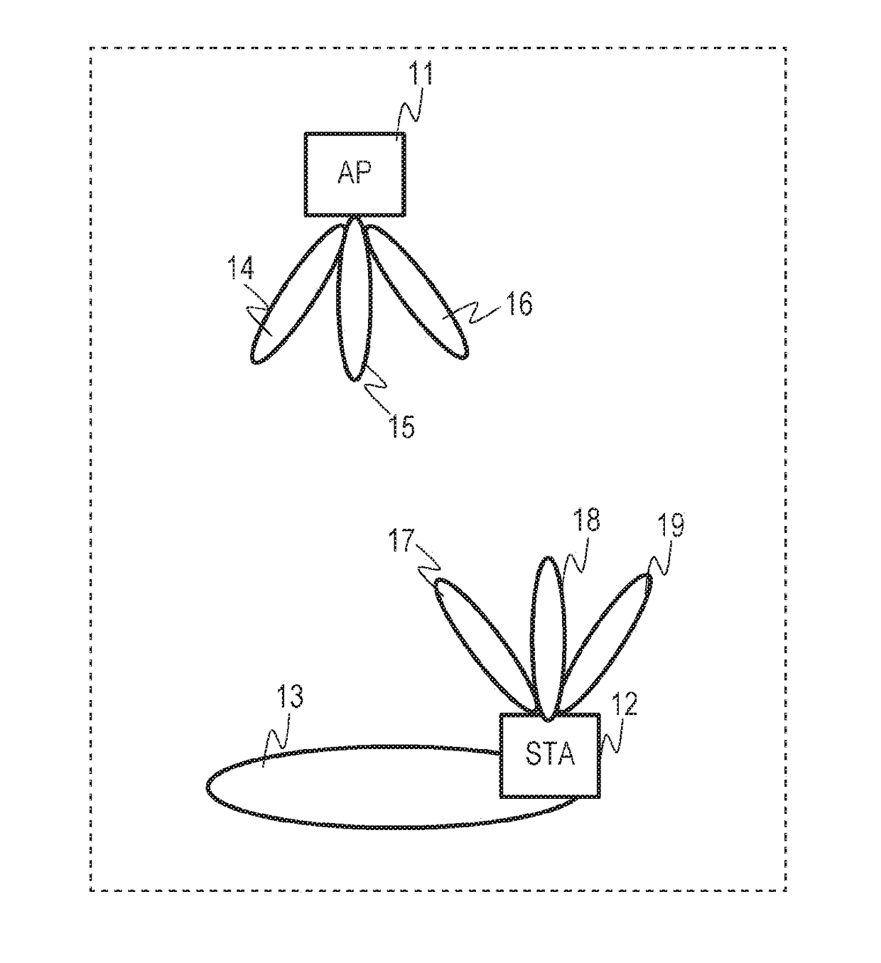
  • Virtual base station apparatus and communication method
  • Virtual base station apparatus and communication method
  • Virtual base station apparatus and communication method

Examples


embodiment

2. Embodiment

2-1. Configuration of Communication System

[0061]FIG. 6 illustrates an example configuration of a millimeter-wave communication system 100 according to this embodiment. In the millimeter-wave communication system 100 according to this embodiment, a plurality of APs cooperate with each other to form a virtual AP. Specifically, a base station apparatus 101 (API) and a base station apparatus 102 (AP2) are connected to each other via a control device 1031 to form a virtual base station apparatus (virtual AP) 103. The AP1 covers a communication area 105 by using beams 108 to 110, and the AP2 covers a communication area 106 by using beams 111 to 113. The virtual AP 103 is capable of covering a communication area 107 having a wider range in which the communication areas 105 and 106 are combined. A terminal (STA) 104 establishes a connection with the virtual AP 103 by using beams 114 to 116.

2-2. Transmission of Training Frames Starting from Virtual AP

[0062]FIG. 7 is a sequence d...


PUM


Abstract

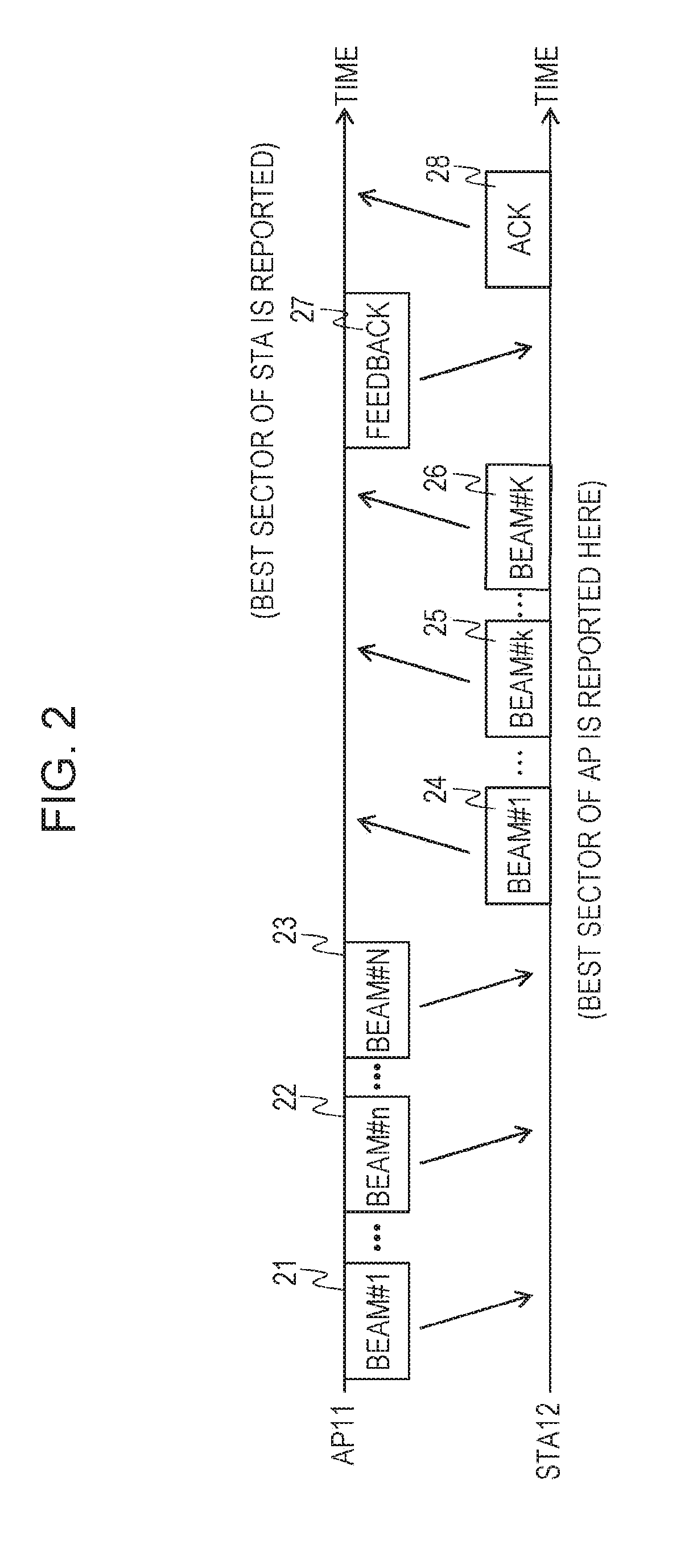
A virtual base station apparatus (virtual AP) formed by a plurality of base station apparatuses (APs) requests a terminal apparatus (STA) to start beamforming training. The terminal apparatus transmits a plurality of first training frames to the virtual base station apparatus. The virtual base station apparatus receives the plurality of first training frames by using the plurality of base station apparatuses, and transmits a plurality of second training frames including information on a training frame received under the best conditions from a first base station apparatus that has received the training frame received under the best conditions to the terminal apparatus. The terminal apparatus receives the plurality of second training frames, and transmits to the virtual base station apparatus a second frame including information on a frame received under the best conditions among the plurality of second received training frames,

Description

BACKGROUND[0001]1. Technical Field[0002]The present disclosure relates to a virtual base station apparatus and a communication method for performing millimeter-wave band communication using beamforming.[0003]2. Description of the Related Art[0004]In recent years, to ensure a bandwidth of 1 GHz or higher to meet rapidly increasing traffic demands, studies have been made on the employment of small base station apparatuses that perform communication by using millimeter wave bands. For example, a communication system (also sometimes referred to as a heterogeneous network) is conceived in which a plurality of small base station apparatuses are located within a communication area of a base station apparatus that performs communication by using microwave bands.[0005]Such small base station apparatuses use millimeter wave bands. Communication using the millimeter wave bands causes propagation loss greater than that using the microwave bands, and it is difficult to extend the arrival range o...

Claims


Application Information

Patent Timeline
IPC IPC(8): H04W16/28H04B7/06H04L12/46
CPCH04W16/28H04B7/0632H04L12/4641H04B7/0617H04W72/046H04W88/08H04W72/27H04B7/022H04B7/063H04B7/0695H04B17/309
Inventor TOMISAWA, YUJISHIRAKATA, NAGANORIMOTOZUKA, HIROYUKIIRIE, MASATAKA
Owner PANASONIC INTELLECTUAL PROPERTY CORP OF AMERICA
Learn More