
Lens assembly and imaging pickup device

Active Publication Date: 2017-09-28
TOKYO VISIONARY OPTICS CO LTD
View PDF2 Cites 5 Cited by
  • Summary
  • Abstract
  • Description
  • Claims
  • Application Information

AI Technical Summary

Benefits of technology

The present invention aims to provide a lens assembly with a lens holder that has low-profileness and is capable of effectively compensating for changes in back focus occurring due to changes in atmospheric temperature. The invention also provides an imaging device that utilizes the lens assembly.

Problems solved by technology

When characteristics of a lens in the lens unit change due to the change in the atmospheric temperature, a change may be occurred in back focus of an optical system of the lens unit, and there may cause a risk of deterioration of image quality such as image blur due to misalignment of the focal point.
As such, when an extended part having sufficient length is formed, the overall height of the imaging device becomes higher, therefore there may be difficult to meet the demand of low-profileness of imaging devices.

Method used


Image

  • Lens assembly and imaging pickup device
  • Lens assembly and imaging pickup device
  • Lens assembly and imaging pickup device

Examples


first embodiment to third embodiment

(Evaluation of First Embodiment to Third Embodiment According to the Present Invention and Comparative Examples 1 and 2)

[0133]The function of compensating for changes in back focus was evaluated for Examples 1 to 3 according to the embodiments, and Comparative Examples 1 and 2 according to a conventional imaging device.

[0134]First, the configuration of Examples 1 to 3 and Comparative Examples 1 and 2 used for evaluation are described.

example 1

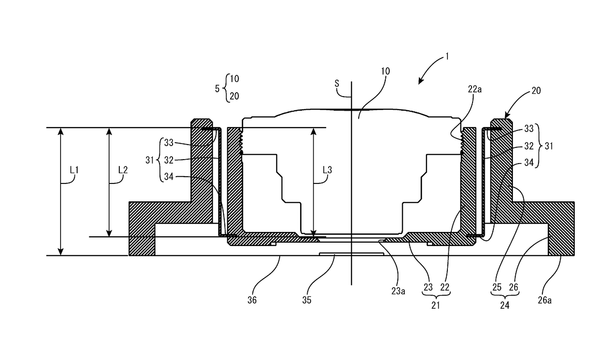
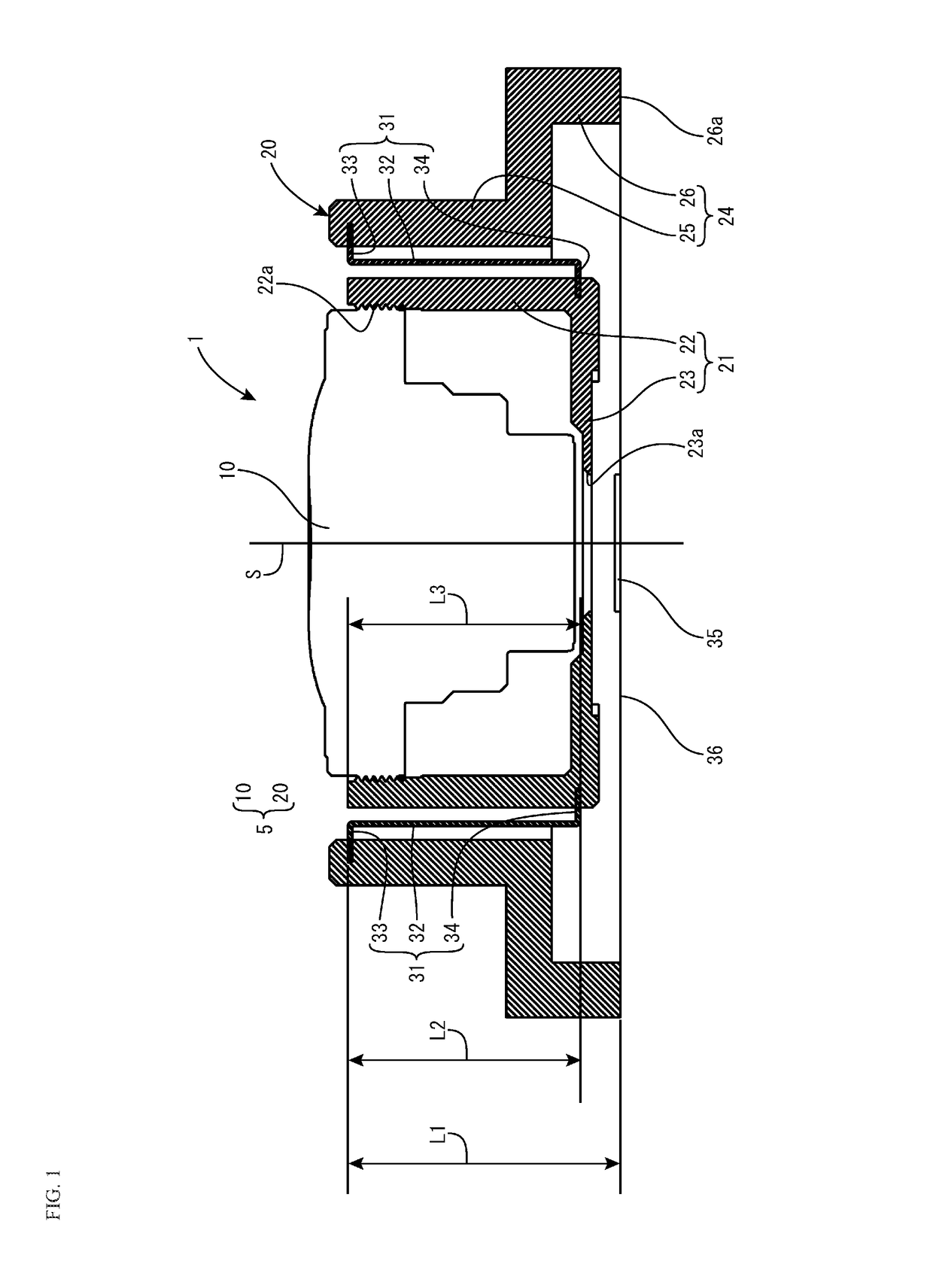
[0135]In Example 1, an imaging device 1 according to the first embodiment described above comprises a lens unit 10 containing an optical system shown in Table 1 below. Regarding Modulation Transfer Function (MTF) of Table 1, S denotes sagittal side, T denotes tangential side, and each value denotes the contrast value (%) for a 120 LP / mm resolution. The focal length f of the overall optical system of the lens unit 10 is 1.66 mm. Further, the lens holder 20 of example 1 has the configuration shown in Table 2. As shown in Table 2, the inner frame 21 and the outer frame 24 are formed from Panlite™ as the material, wherein the thermal expansion coefficient α1 and the thermal expansion coefficient α3 are 70×10−6 / ° C. The linking frame 31 is formed from aluminum bronze as the material, wherein the thermal expansion coefficient α2 is 16.5×10⁻⁶ / ° C. The distance L1 in the direction of the optical axis from the attachment location of the upper flange part 33 to the lower end surface 26a of th...

example 2

[0136]In Example 2, the imaging device 2 according to the second embodiment described above comprises a lens unit 10 containing an optical system shown in Table 1 above. Further, the lens holder 20A of Example 2 has a configuration shown in Table 3. As shown in Table 3, the inner frame 21, the middle frame 27, and the outer frame 24 are formed from Panlite™ as the material, wherein the thermal expansion coefficient α1, the thermal expansion coefficient α3, and the thermal expansion coefficient α5 are 70×10−6 / ° C., and the first linking frame 41 and the second linking frame 45 are formed from aluminum bronze as the material, wherein the thermal expansion coefficient α2 and the thermal expansion coefficient α4 are 16.5×10⁻⁶ / ° C. The distance L1 in the direction of the optical axis from the attachment location of the upper flange part 43 of the first linking part 41 to the lower end surface 26a on the holding frame 24 is 5.3 mm, the distance L2 in the direction of the optical axis from...


PUM


Abstract

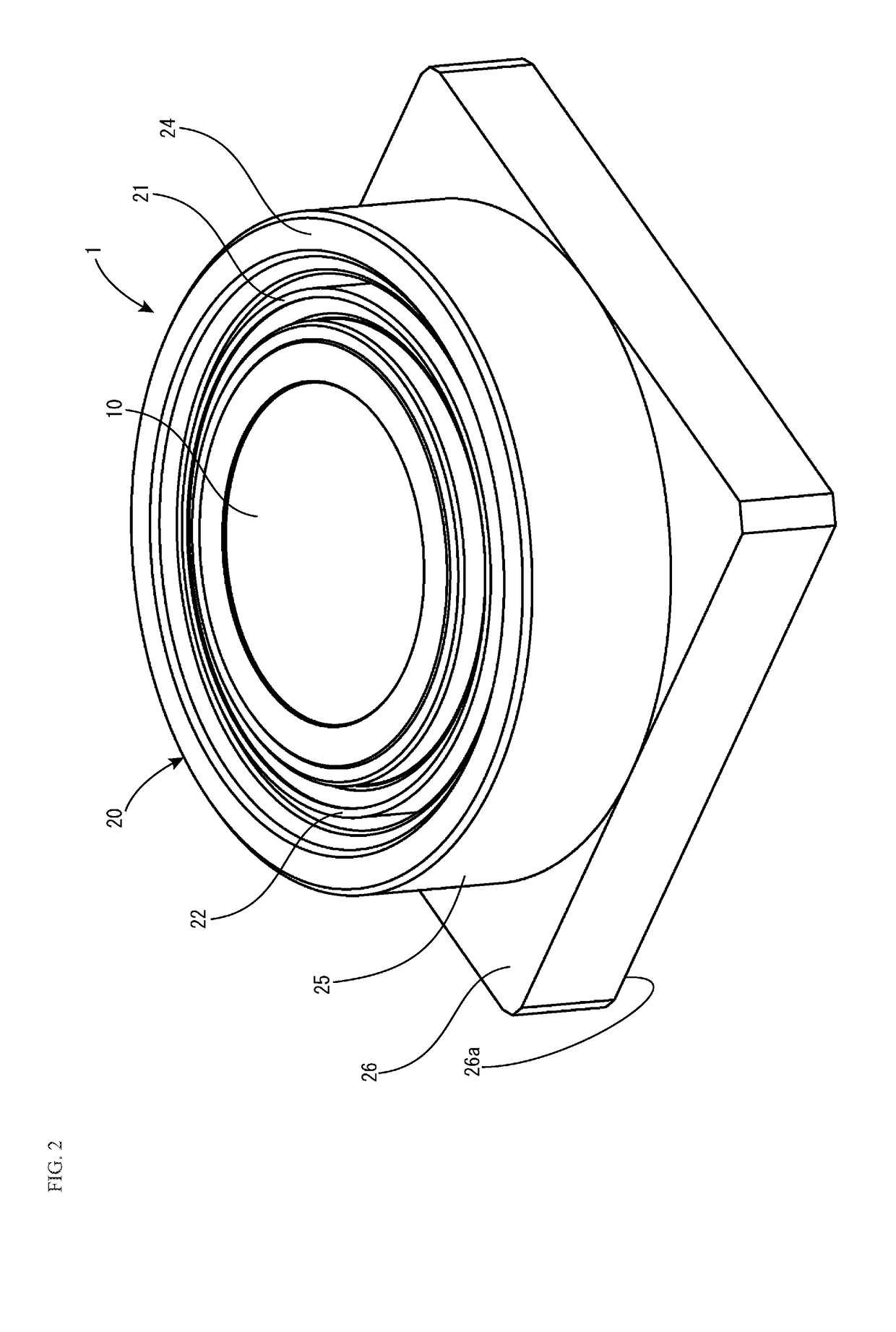
A lens assembly and an imaging device for realizing low-profileness, and for effectively compensating a change in back focus generated by a change in atmospheric temperature. A lens holder contained in a lens assembly of an imaging device includes an inner frame on which a lens unit is attached, a holding frame provided with a lower end surface fixing a positional relationship with an image sensor, a linking frame for linking the inner frame and the holding frame. The lens holder extends and contracts so that the inner frame and the holding frame distance the lens unit from the image sensor when back focus of the lens unit extends due to change in atmospheric temperature, and brings the lens unit closer to the image sensor when the back focus contracts.

Description

FIELD OF THE INVENTION[0001]The present invention relates to a lens assembly having a lens unit for forming an image of an object on an image sensor and a lens holder for holding the lens unit, particularly to a lens assembly having a lens holder which compensates for a change in back focus of an optical system of a lens unit that accompanies a change in atmospheric temperature, and to an imaging device which has the lens assembly.DESCRIPTION OF THE RELATED ART[0002]A fixed focus imaging device has, for example, a lens unit having a plurality of lenses and a barrel for containing the lenses, and a lens holder for holding the lens unit. In an imaging device, the lens holder directly or indirectly fixes the lens unit onto a substrate onto which an image sensor, such as a CCD sensor or C-MOS sensor, is mounted. That is, the mutual positional relationship of the image sensor and the lens unit is fixed by the lens holder. When characteristics of a lens in the lens unit change due to the ...

Claims


Application Information

Patent Timeline
IPC IPC(8): G02B7/02H04N5/225
CPCG02B7/022G02B7/021G02B7/028H04N5/2254H04N23/57H04N23/55
Inventor SAKUMA, AKIOIKEDA, MAKOTO
Owner TOKYO VISIONARY OPTICS CO LTD
Learn More