
Phase adjusting function evaluating method, transmission margin measuring method, information processing apparatus, program and computer readable information recording medium

Inactive Publication Date: 2008-07-24
FUJITSU LTD
View PDF5 Cites 5 Cited by
  • Summary
  • Abstract
  • Description
  • Claims
  • Application Information

AI Technical Summary

Benefits of technology

[0031]The present invention has been devised in consideration of the above-mentioned situation, and an object of the present invention is to provide a configuration such that phase adjustment operation in a phase adjusting circuit can be easily and positively evaluated.
[0033]Thus, the predetermined phase amount thus added to the clock signal or the data signal is changed in the predetermined manner, then, information of resulting operation of the phase adjusting part is stored, and thereby, it is possible to effectively simulate a change in a phase difference between the input clock signal and the input data signal, which phase difference may occur in regular operation. Thereby, it is possible to easily and positively prove the phase adjusting function of the phase adjusting part.
[0034]Thus, according to the present invention, it is possible to easily and positively prove the phase adjusting function of the phase adjusting circuit, and as a result, when some trouble occurs in the phase adjusting function of the phase adjusting circuit, this fact can be positively detected, to be appropriately dealt with. Thus, it is possible to effectively improve reliability in data transmission in a computer system.

Problems solved by technology

Immediately after a power supply is started up, such a phase relationship may occur between the clock signal and the data that proper data transmission may not be achieved.
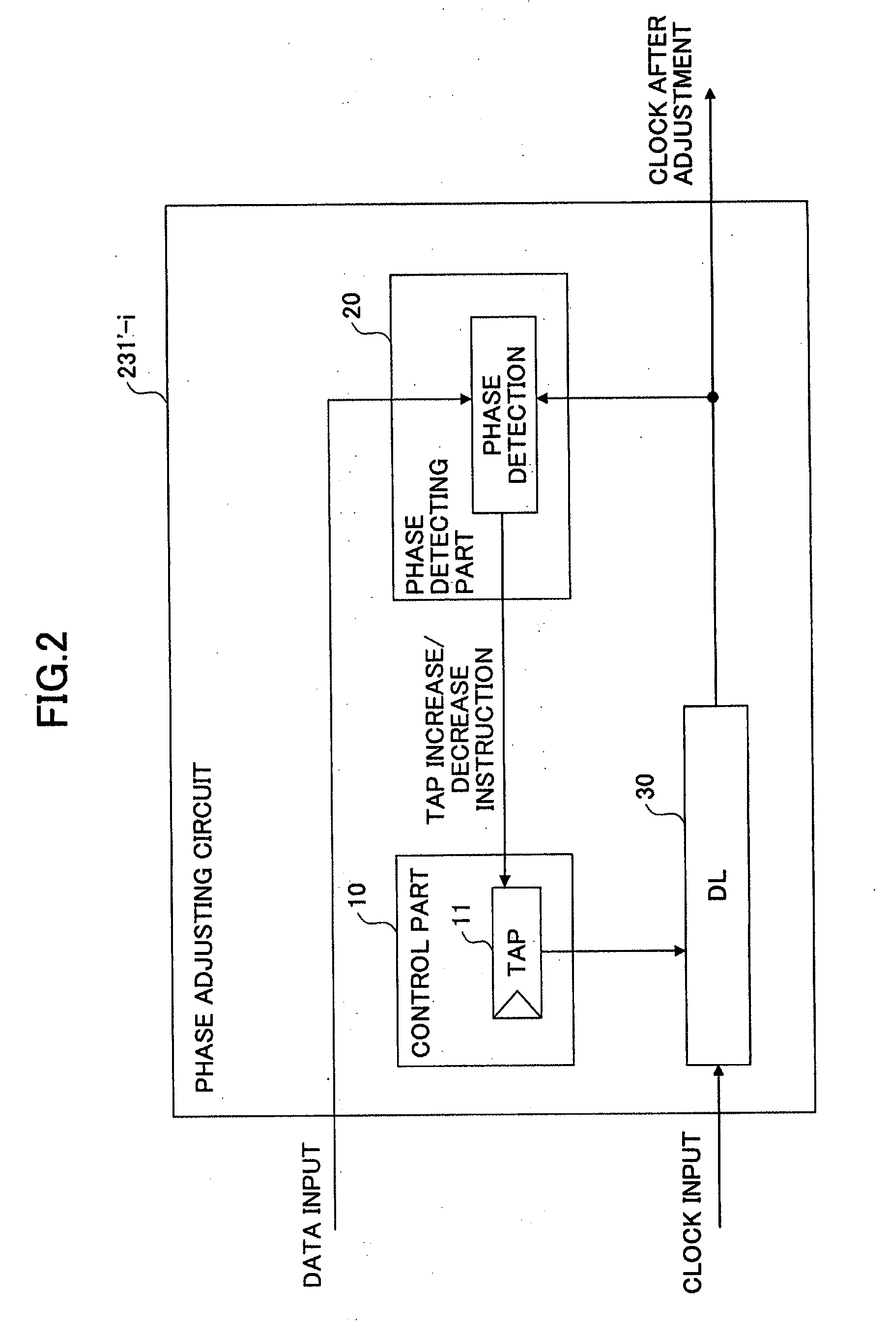
As a result, in this case, the external controller recognizes that the initial phase adjustment operation carried out by each phase adjusting circuit 231′-i results in failure.
In such a case, an operation failure may occur depending on a condition of the ambient temperature, a power supply voltage, frequency, interconnect wiring lengths, or such.
Therefore, a considerable time may be required for the measurement for all the signals when the number of signal lines is large.

Method used


Image

  • Phase adjusting function evaluating method, transmission margin measuring method, information processing apparatus, program and computer readable information recording medium
  • Phase adjusting function evaluating method, transmission margin measuring method, information processing apparatus, program and computer readable information recording medium
  • Phase adjusting function evaluating method, transmission margin measuring method, information processing apparatus, program and computer readable information recording medium

Examples


Embodiment Construction

[0051]An embodiment of the present invention has a configuration such as to automatically evaluate a phase adjusting function of each of a plurality of phase adjusting circuits, which are controllable by firmware. In this configuration, operation of each of the phase adjusting circuits can be automatically proved, and a transmission margin can be automatically measured. As a result, it is possible to very easily carry out evaluation of the apparatus and analysis of a trouble.

[0052]Each of the plurality of phase adjusting circuits can operate separately.

[0053]Further, a register which each of the plurality phase adjusting circuits has can be read or written by the firmware during operation of the phase adjusting circuit.

[0054]Further, operation of the phase adjusting circuit can be controlled by the firmware, resulting operation is then analyzed, and thus, evaluation of the phase adjusting function of the phase adjuring circuit can be automatically carried out.

[0055]A configuration o...


PUM


Abstract

A phase amount added to a clock signal or a plurality of data signals for adjusting a phase relationship therebetween in a reception apparatus is changed, and, a result of the phase adjusting operation is stored when the phase amount added to the clock signal or the plurality of data signals is changed.

Description

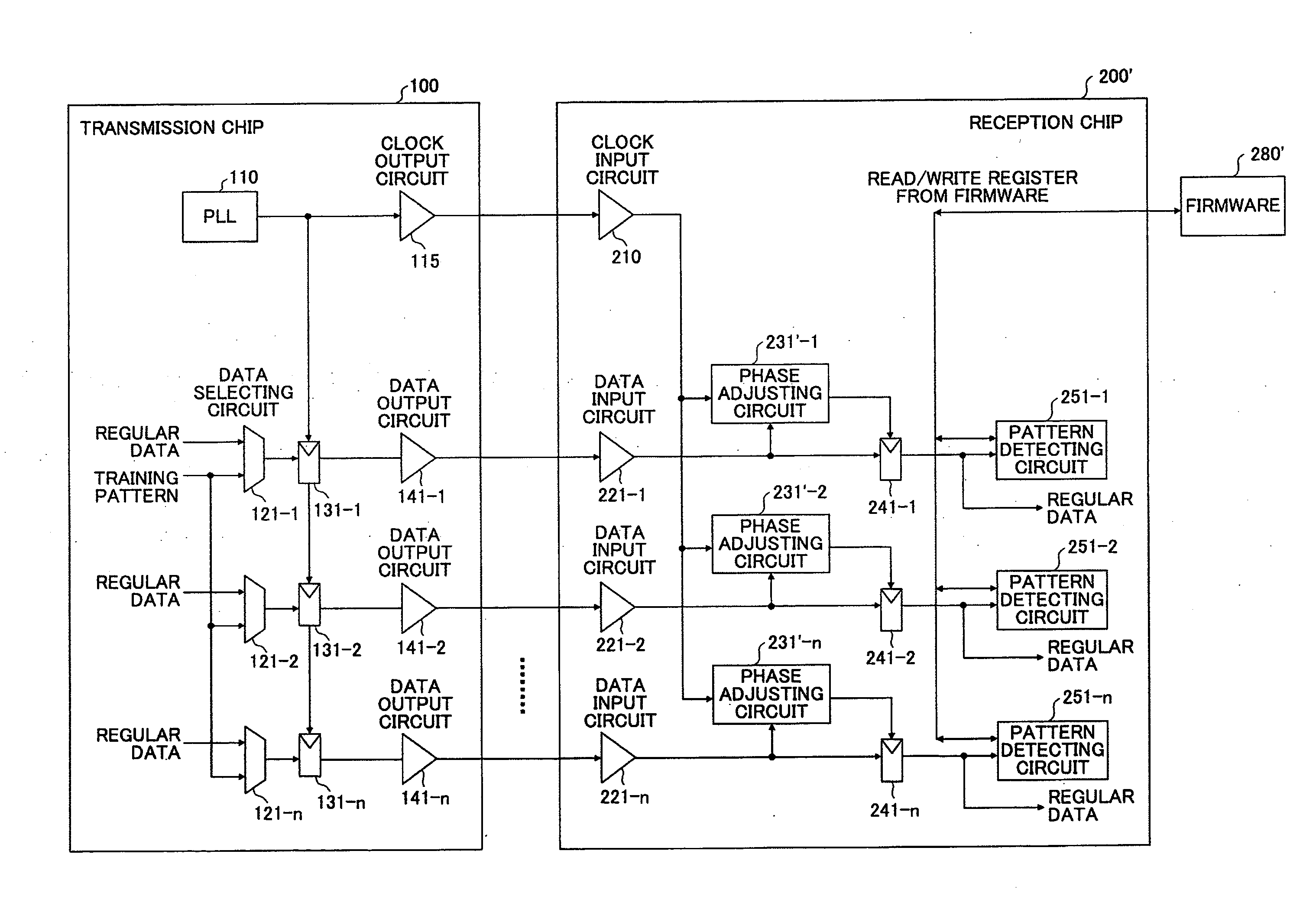
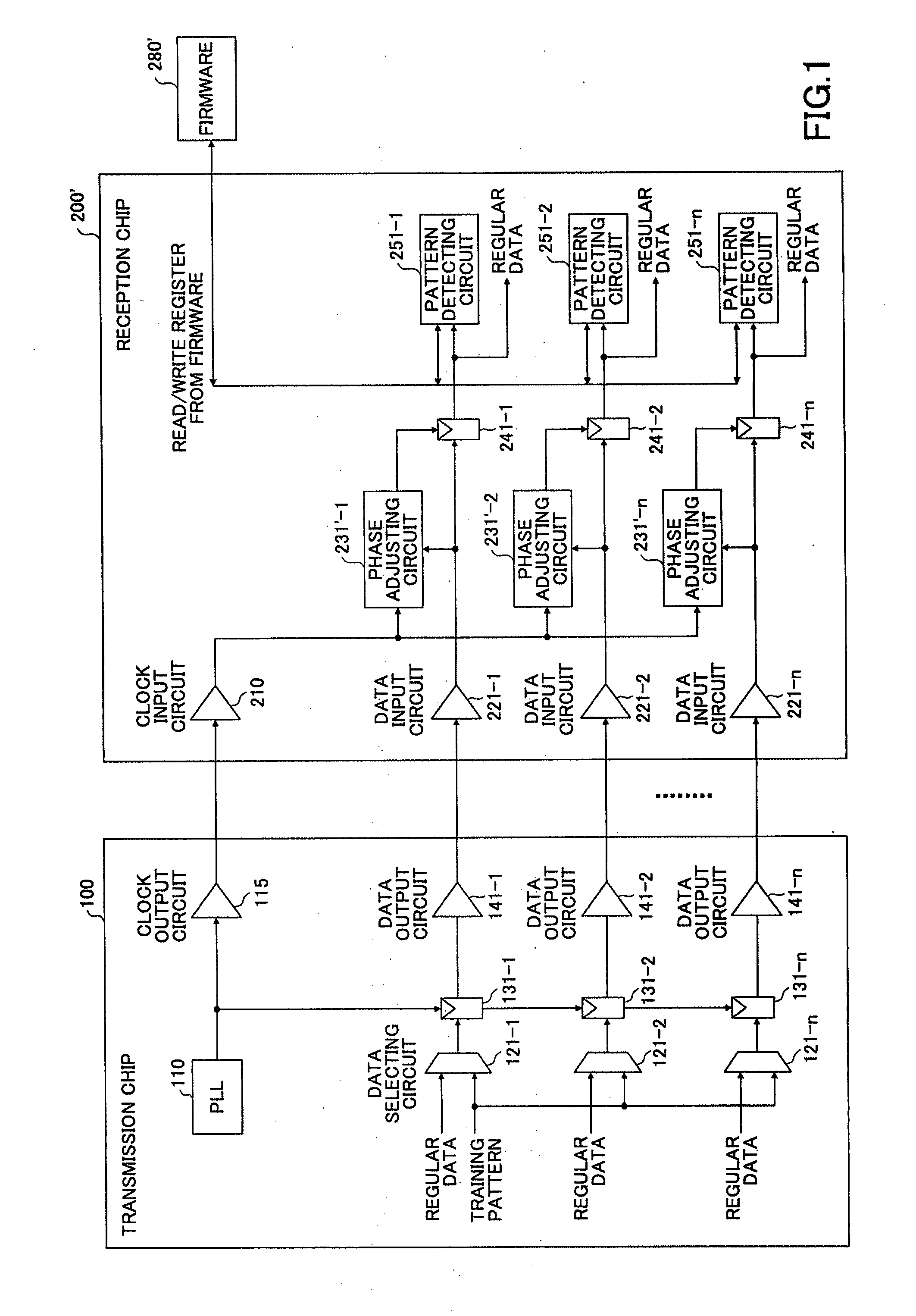
BACKGROUND OF THE INVENTION[0001]1. Field of the Invention[0002]The present invention relates to a phase adjusting function evaluating method, a transmission margin measuring method, an information processing apparatus, a program and a computer readable information recording medium.[0003]2. Description of the Related Art[0004]FIG. 1 shows a block diagram illustrating a configuration of a transmission chip and a reception chip in one example of the related art.[0005]These transmission chip 100 and reception chip 200′ are silicon chips configuring a semiconductor integrated circuit applied to, for example, a part of a computer system, described later with reference to FIG. 5, which part carries out data transmission between a system board 1-i and a memory system interconnect 3, or between the memory system interconnect 3 and an IO unit 2-i. [0006]The transmission chip 100 includes a phase synchronization circuit (PLL) 110, a clock output circuit 115, data output circuits 141-1 through...

Claims


Application Information

Patent Timeline
IPC IPC(8): H04L7/00
CPCG06F1/10H03K5/135H03L7/07H04L7/0037H04L7/0008H04L7/02H04L7/0041H03L7/0812H04L7/08
Inventor NAKAYAMA, HIROSHIOSANO, HIDEKAZU
Owner FUJITSU LTD
Learn More