Remote load control device capable of orientation detection

a load control and remote control technology, applied in the direction of mechanical control devices, pulse techniques, instruments, etc., can solve the problems of cost prohibitive for the average consumer, the average consumer may not feel comfortable performing the electrical wiring required in such an installation, and the cost of hiring an electrical contractor

Active Publication Date: 2017-09-28
LUTRON TECH CO LLC
View PDF4 Cites 88 Cited by
  • Summary
  • Abstract
  • Description
  • Claims
  • Application Information

AI Technical Summary

Benefits of technology

[0007]The control unit may include a user interface (e.g., a symmetric user interface), an orientation sensing circuit, and a communication circuit (e.g., a wireless communication circuit). The user interface of the control unit comprises a capacitive touch circuit. The control unit configured to determine an orientation of the control unit via the orientation sensing circuit, and translate a user input from the user interface into control data based on the orientation of the control unit, where the control data configured to control an electrical load of the load control system. The control unit is also configured to cause the communication circuit to transmit a control signal comprising the control data. The control data may be configured to control an intensity or a color of a lighting load of the load control system.
[0008]The orientation sensing circuit may include a switch that is configured to be closed (e.g., conductive) when the control unit is in a first orientation and open (e.g., non-conductive) when the control unit is in a second orientation. The switch may include an electrical contact pad and / or a shorting member, a tactile switch and / or a protrusion, a gravity switch, a mercury switch, etc. The orientation sensing circuit may include a ball and a light emitting diode (LED) sensor, a photosensitive device, an optocoupler that comprises an infra-red (IR) light emitting diode (LED) and a photodiode, an inductive sensor, a hall-effect sensor circuit, a manually operated switch, an accelerometer, a gyroscope, and / or the like.
[0009]The control unit may be configured to automatically determine the orientation of the control unit upon the control unit being attached to the mounting structure. The control unit may be configured to determine the orientation of the control unit each time the control unit wakes up from an off or sleep state. The control unit may be configured to translate user inputs that correspond to on and off commands of the electrical load to respective control data based on the orientation of the control unit. Alternatively or additionally, the control unit may be configured to translate user inputs that correspond to raise and lower commands of the electrical load to respective control data based on the orientation of the control unit.
[0010]The user interface may be configured to provide, via visual indicators of the control unit, a visual indication of an amount of power delivered to the electrical load based on the orientation of the control unit. For example, the user interface may be configured to emit an amount of light that corresponds to the amount of power delivered to the electrical load based on the orientation of the control unit. Alternatively or additionally, the user interface comprises a plurality of light emitting diodes (e.g., arranged as a light bar) that are arranged in a linear array and that are configured to provide the visual indication based on the orientation of the control unit. For example, the array of light emitting diodes may defines a first end of the visual indication that corresponds to a high-end amount of power and an opposed second end of the visual indication that corresponds to a low-end amount of power. The control unit may be configured to determine the relative locations of the first and second ends of the visual indication based on the orientation of the control unit.
[0011]In examples where the LEDs are arranged as a light bar, the light bar may define a starting point of the visual indication that corresponds to low-end amount of power and an ending point of the visual indication that corresponds to a high-end amount of power, and the control unit may be configured to determine the relative locations of the starting point and ending point of the visual indication based on the orientation of the control unit. In some examples, the starting point and the ending point are the same location or adjacent locations on the light bar. Moreover, the starting point and the ending point are located at a bottom of the light bar.
[0012]The control unit may be configured to receive the orientation during a configuration mode of the control unit, for example, when the control unit is placed into the configuration mode via a unique user input via the user interface and / or placed into the configuration mode via an external device. The remote control device may also be paired with an electrical load of the load control system during the configuration mode. The control unit may be configured to receive the orientation of the control unit from an external device (e.g., smartphone, tablet, etc.) via the communication circuit. The external device may be configured to determine the orientation of the control unit using a camera of the external device. In such instances, the control unit may be configured to illuminate light sources of the control unit in a unique pattern to communicate the orientation of the control unit.

Problems solved by technology

An average consumer may not feel comfortable performing the electrical wiring required in such an installation.
Accordingly, such a procedure may typically be performed by an electrical contractor or other skilled installer, but hiring an electrical contractor may be cost prohibitive to the average consumer.

Method used


Image

  • Remote load control device capable of orientation detection
  • Remote load control device capable of orientation detection
  • Remote load control device capable of orientation detection

Examples


Embodiment Construction

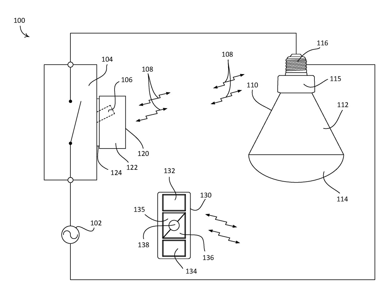
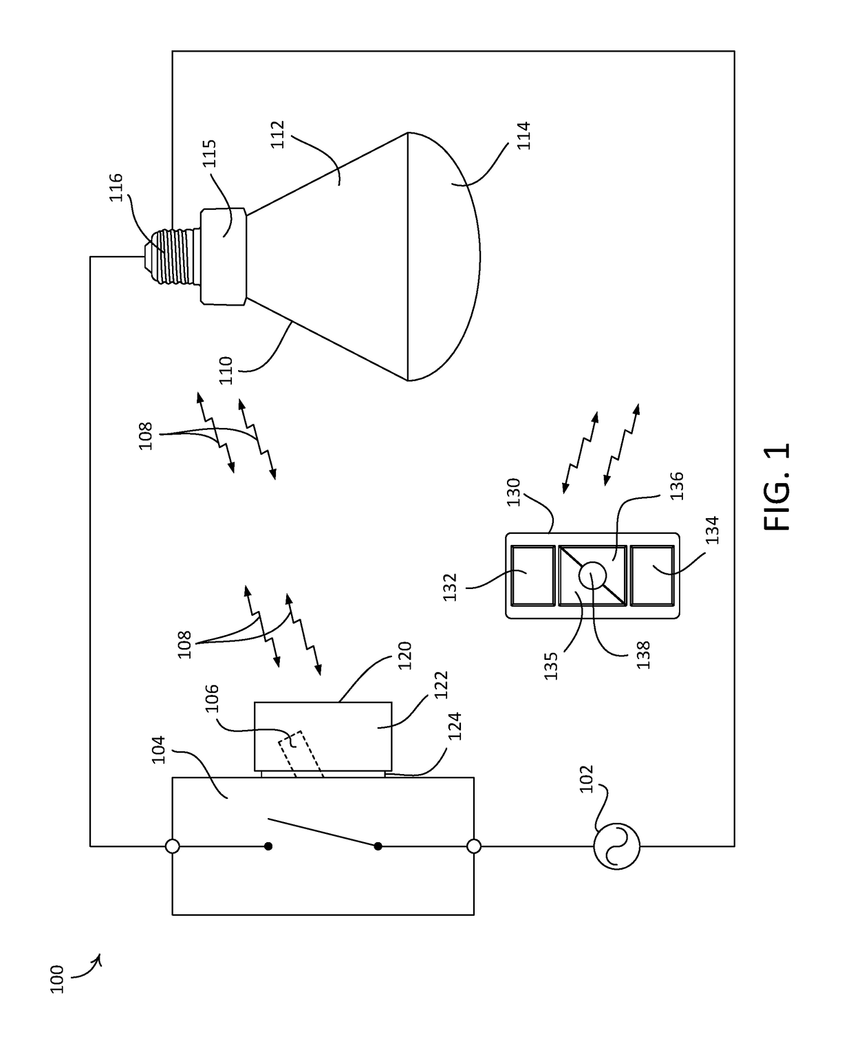
[0057]FIG. 1 depicts an example load control system 100. As shown, the load control system 100 may be configured as a lighting control system that may include an electrical load (e.g., such as a controllable light source 110), and a remote control device 120 (e.g., such as a battery-powered rotary remote control device). The load control system 100 may include a standard, single pole single throw (SPST) maintained mechanical switch 104 (e.g., a “toggle switch” or a “light switch”). The switch 104 may be in place prior to installation of the remote control device 120 (e.g., pre-existing in the load control system 100). The switch 104 may be electrically coupled (e.g., in series) between an alternating current (AC) power source 102 and the controllable light source 110. The switch 104 may include a toggle actuator 106 that may be actuated to toggle (e.g., to turn on and / or turn off) the controllable light source 110. The controllable light source 110 may be electrically coupled to the...


PUM


Abstract

A remote control device is provided that is configured for use in a load control system that includes one or more electrical loads. The remote control device includes a mounting structure and a control unit, and the control unit is configured to be attached to the mounting structure in a plurality of different orientations. The control unit includes a user interface, an orientation sensing circuit, and a communication circuit. The control unit is configured to determine an orientation of the control unit via the orientation sensing circuit. The control unit is also configured to translate a user input from the user interface into control data to control an electrical load of the load control system based on the orientation of the control unit and/or provide a visual indication of an amount of power delivered to the electrical load based on the orientation of the control unit.

Description

CROSS-REFERENCE TO RELATED APPLICATIONS[0001]This application claims the benefit of Provisional U.S. Patent Application No. 62 / 312,863, filed Mar. 24, 2016, Provisional U.S. Patent Application No. 62 / 345,222, filed Jun. 3, 2016, Provisional U.S. Patent Application No. 62 / 345,449, filed Jun. 3, 2016, Provisional U.S. Patent Application No. 62 / 345,464, filed Jun. 3, 2016, Provisional U.S. Patent Application No. 62 / 356,007, filed Jun. 29, 2016, Provisional U.S. Patent Application No. 62 / 356,179, filed Jun. 29, 2016, Provisional U.S. Patent Application No. 62 / 356,288, filed Jun. 29, 2016, and Provisional U.S. Patent Application No. 62 / 411,223, filed Oct. 21, 2016, the disclosures of which are incorporated herein by reference in their entireties.BACKGROUND[0002]A load control system may include one or more electrical loads that a user may wish to control via a single load control device. These electrical loads may include, for example, lighting loads, HVAC units, motorized window treatme...

Claims


Application Information

Patent Timeline
Patent Type & Authority Applications(United States)
IPC IPC(8): G08C17/02G01D5/34G01R21/00G01D5/14G01D5/02H01H35/02G01D5/20H05B44/00
CPCG08C17/02H01H35/02G01D5/34G01D5/20G08C2201/32G01D5/02G01R21/00H01H2231/032G01D5/145H05B47/10Y04S20/14G06F3/0488H01H9/0235H01H9/025H01H9/287H01H2300/03G06F3/04847G06F3/04883G06F2203/04808H01H9/02H01H9/0207H02G3/14H05B47/175Y02B20/30Y02B90/20H05B47/165H05B47/115H05B47/195H05B45/20H05B45/31Y02B20/40G06F3/03547G06F3/017H01H11/00H01H23/16H01H2223/034H03K17/962H05B45/00H05B47/19H05B47/105H01H9/16H05B47/11G05G1/08H01H19/14H01H23/12H03K17/96
Inventor DIMBERG, CHRISGAGE, ALEXANDER WADEHARTE, MATTHEW V.KILLO, JASON C.KRESCHOLLEK, BRAD MICHAELMCDONALD, MATTHEW PHILIPTWADDELL, DANIEL L.
Owner LUTRON TECH CO LLC
Why Eureka
Try Eureka