Magnetic circuit and loudspeaker using same

a technology of magnetic circuit and loudspeaker, which is applied in the direction of transducer types, electrical transducers, transducer diaphragms, etc., can solve the problems of large distortion of the sound of the loudspeaker, disturbance of the vibration of the voice coil, and so as to reduce the leakage of magnetic flux at the second lower end, increase the magnetic flux density between the first upper end and the second upper end, and reduce the effect of nois

Inactive Publication Date: 2017-09-28
PANASONIC INTELLECTUAL PROPERTY MANAGEMENT CO LTD
View PDF1 Cites 2 Cited by
  • Summary
  • Abstract
  • Description
  • Claims
  • Application Information

AI Technical Summary

Benefits of technology

[0010]In the above configuration, the first facing part has a first upper end and a first lower end. Note that the first lower end is disposed at a position that is closer to the bottom part than the first upper end is. Further, the second facing part has a second upper end and a second lower end. The second upper end is disposed so as to be separated by a first distance from the first upper end. Meanwhile, the second lower end is disposed so as to be separated by a second distance from the first lower end. Moreover, the second lower end is disposed at a position that is closer to the bottom part than the second upper end is. The second distance is made greater than the first distance. Accordingly, the intended object can be achieved.
[0011]As described above, according to the present disclosure, since the second distance is greater than the first distance, magnetic resistance between the first upper end and the second upper end is smaller than magnetic resistance between the first lower end and the second lower end. Hence a magnetic flux density between the first upper end and the second upper end can be increased. As a result, the magnetic flux density between the first upper end and the second upper end increases. Further, the leakage of the magnetic flux at the second lower end can be made small. As a result, bias of the magnetic flux density distribution in the magnetic gap can be made small, and hence distortion of sound of the loudspeaker can be made small.

Problems solved by technology

However, in the conventional magnetic circuit, magnetic flux leaks to the center pole from a lower surface that faces a bottom surface in the magnet.
When the voice coil inserted into the conventional magnetic circuit as thus described perpendicularly vibrates, disturbance occurs in the vibration of the voice coil due to the bias of the magnetic flux density distribution in the magnetic gap.
There has thus been a problem of large distortion of sound of the loudspeaker.

Method used


Image

  • Magnetic circuit and loudspeaker using same
  • Magnetic circuit and loudspeaker using same
  • Magnetic circuit and loudspeaker using same

Examples


first exemplary embodiment

[0027]Hereinafter, loudspeaker 51 in the present exemplary embodiment is described with reference to the drawings.

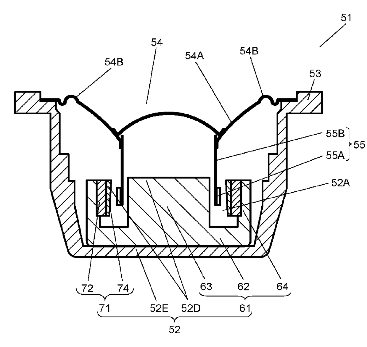
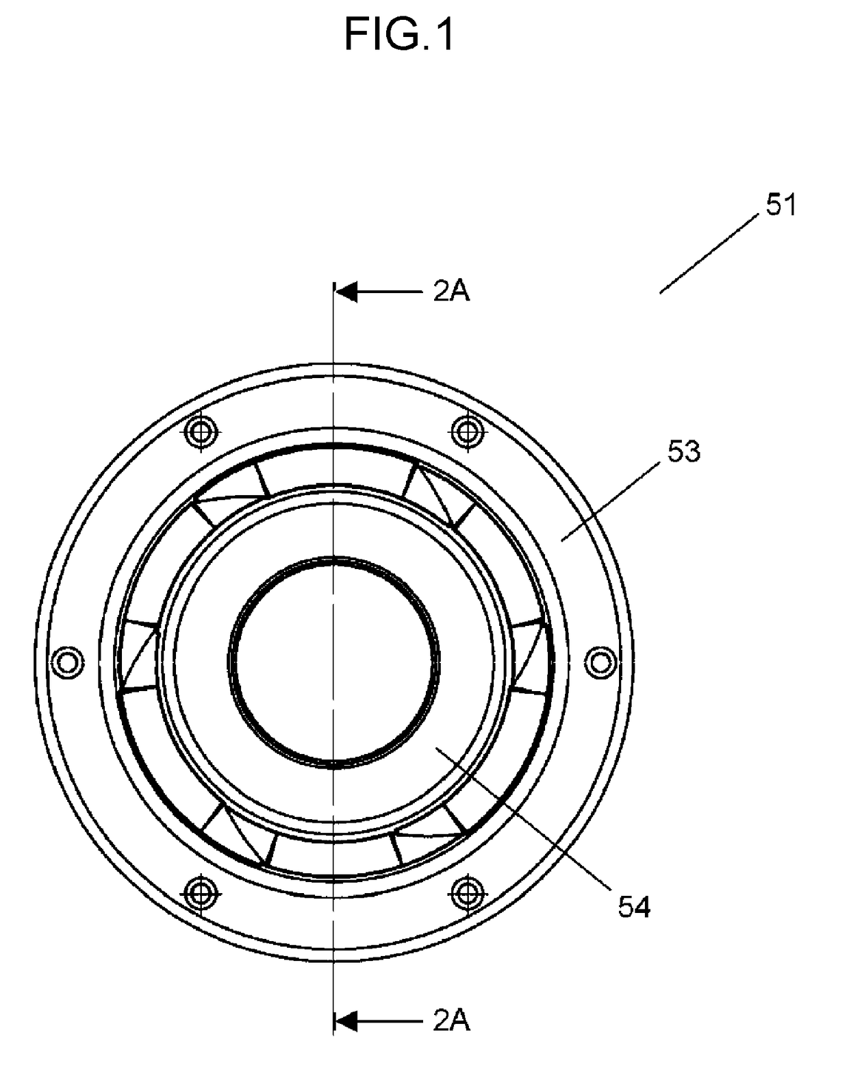
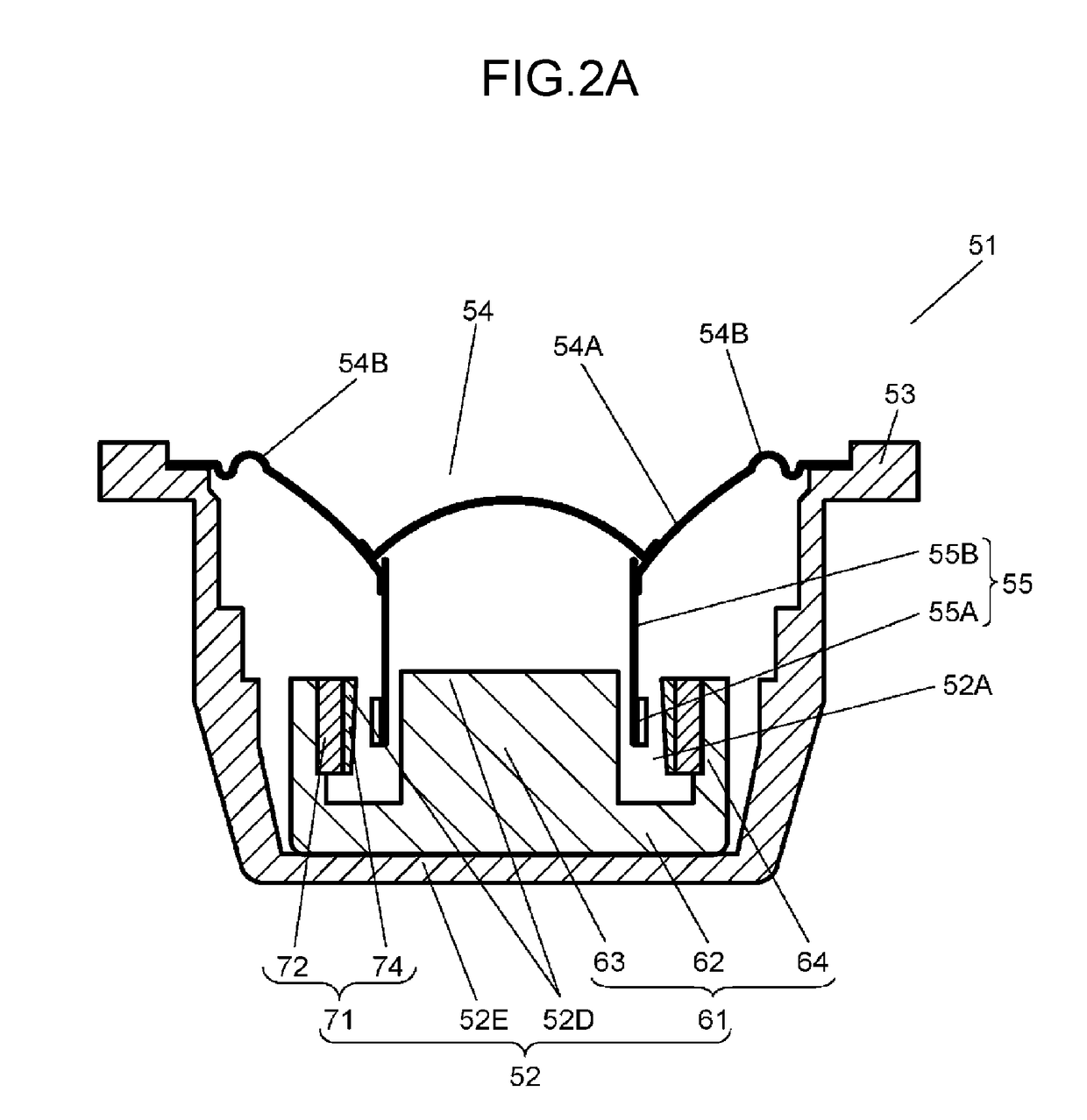
[0028]FIG. 1 is a top view of loudspeaker 51 according to the present exemplary embodiment. FIG. 2A is a sectional view of loudspeaker 51. FIG. 3 is an enlarged sectional view of magnetic circuit 52 included in loudspeaker 51. Note that FIG. 2A shows a sectional view obtained by cutting along sectional line 2A-2A of FIG. 1.

[0029]Loudspeaker 51 includes magnetic circuit 52 formed with magnetic gap 52A, frame 53, diaphragm 54, and voice coil body 55. The outer periphery of diaphragm 54 is coupled to frame 53. Voice coil body 55 has a first end part and a second end part. The first end part of voice coil body 55 is coupled to diaphragm 54. Meanwhile, the second end part of voice coil body 55 is inserted into magnetic gap 52A.

[0030]Magnetic circuit 52 includes yoke 61 and magnetic part 71. Yoke 61 includes bottom part 62 and first facing part 81. Bottom part 62 includes uppe...

second exemplary embodiment

[0080]Hereinafter, a loudspeaker in a second exemplary embodiment, especially magnetic circuit 152, is described with reference to the drawings. A configuration of the loudspeaker other than magnetic circuit 152 is similar to the configuration of loudspeaker 51 of the first exemplary embodiment.

[0081]FIG. 8 is a sectional view of magnetic circuit 152. Magnetic circuit 152 is an inner magnet type. Magnetic circuit 152 includes yoke 161 and magnetic part 171. Magnetic part 171 includes magnet 172 and first plate 174. Yoke 161 includes bottom part 62 and cylindrical part 64. Hence magnet 172 is mounted at a central portion of upper surface 62A of bottom part 62. First pole 72A of magnet 172 is magnetically coupled with bottom part 62. First plate 174 is coupled with second pole 72B of magnet 172.

[0082]Magnet 172 has a columnar shape, and first plate 174 has a flat shape. Note that a shape of magnetic circuit 152 seen from above preferably has a circular shape. In this case, magnet 172 ...

third exemplary embodiment

[0084]Hereinafter, a loudspeaker in a third exemplary embodiment, especially a magnetic circuit, is described with reference to the drawings.

[0085]Hereinafter, the loudspeaker in the third exemplary embodiment, especially magnetic circuit 252, is described with reference to the drawings. A configuration of the loudspeaker other than magnetic circuit 252 is similar to the configuration of loudspeaker 51 of the first exemplary embodiment.

[0086]FIG. 10 is a sectional view of magnetic circuit 252. Magnetic circuit 252 is an outer magnet type. Magnetic circuit 252 includes yoke 261 and magnetic part 271. Yoke 261 includes bottom part 62 and center pole 63. In this case, each of magnet 272 and first plate 274 has an annular shape and is formed with a through hole at a central portion. Note that a shape of magnetic circuit 252 seen from above preferably has a circular shape. In this case, magnet 272 has a cylindrical shape. First plate 274 has a disk shape.

[0087]First pole 72A of magnet 27...


PUM


Abstract

An object of the present disclosure is to provide a loudspeaker with small distortion. In order to achieve the object, a magnetic circuit of the present disclosure includes a yoke having a first facing part and a magnetic part having a second facing part. The magnetic part supplies magnetic force to a magnetic gap. The second facing part faces the first facing part through a magnetic gap. A second upper end of the second facing part is disposed so as to be separated by a first distance from a first upper end of the first facing part. Meanwhile, a second lower end of the second facing part is disposed so as to be separated by a greater distance than the first distance from a first lower end of the first facing part.

Description

TECHNICAL FIELD[0001]The present disclosure relates to a magnetic circuit mounted in various types of audio equipment and a loudspeaker using the same.BACKGROUND ART[0002]Hereinafter, a conventional magnetic circuit is described. The conventional magnetic circuit includes a yoke and a magnet. The magnet has an annular shape, and includes a first pole provided on an inner periphery and a second pole provided on an outer periphery. The magnet is magnetized from the first pole toward the second pole in a radial direction. The yoke includes a bottom part and a center pole. The center pole is provided at a central portion of the bottom part. Further, the center pole perpendicularly stands from the bottom part.[0003]The second pole of the magnet is coupled with the yoke. Meanwhile, the first pole of the magnet is disposed facing a side surface of an outer periphery of the center pole. A magnetic gap is formed between the first pole of the magnet and the side surface of the outer periphery...

Claims


Application Information

Patent Timeline
Patent Type & Authority Applications(United States)
IPC IPC(8): H04R9/06H04R7/18H04R7/12H04R9/02
CPCH04R9/06H04R9/025H04R2400/11H04R7/127H04R7/18H04R9/02H04R2209/022
Inventor KUZE, MITSUKAZUINOUE, HIDEAKIKOURA, SATOSHISHIBUYA, TOMONORIDAN, TAKAYUKIITANO, TETSUSHI
Owner PANASONIC INTELLECTUAL PROPERTY MANAGEMENT CO LTD
Why Eureka
Try Eureka