Electroacoustic transducer

a transducer and electroacoustic technology, applied in the direction of transducer details, electrical transducers, plane diaphragms, etc., can solve the problems of difficult to fix small magnets with pp tape or adhesive agents, low sound energy, and less versatility of products, so as to reduce the volume of magnets used, increase the effect of magnetic flux density and effective action

Active Publication Date: 2011-11-22
HANADA AKITO
View PDF9 Cites 2 Cited by
  • Summary
  • Abstract
  • Description
  • Claims
  • Application Information

AI Technical Summary

Benefits of technology

[0085]As described above, according to an electroacoustic transducer of the present invention, the following advantageous effects may be brought about.
[0086]According to the first aspect of the invention, the following effects may be brought about.
[0087](1) By using a magnet plate magnetized in three directions and a magnet plate magnetized in two directions, magnetic fluxes in the radius direction along the vibration plane of an acoustic diaphragm may be effectively generated, it is possible to secure an area having high magnetic flux densities for effective action at a wide range. Accordingly, the magnetic flux densities for effective action are made higher than in a magnet plate magnetized in the radius direction, wherein it is possible to improve the performance of a speaker, which was insufficient, and at the same time, the value of Q (Resonance sharpness) of a low frequency range speaker, which becomes too high, may be lowered, wherein it is possible to provide an electroacoustic transducer that is excellent in practicability.
[0088](2) A magnet plate magnetized in three directions distributes magnetic fluxes for effective action of the outer circumference side area and the inner circumference side area, which are not used in an acoustic diaphragm, to an effective area used in an acoustic diaphragm, and may increase the magnetic flux densities for effective action as the entirety. In addition, by narrowing the area used, the magnetic flux densities for effective action may be further increased intensively, wherein it is possible to provide an electroacoustic transducer that may effectively increase the performance and sensitivity and is excellent in efficiency.
[0089](3) A magnet plate magnetized in two directions may narrow the area of magnets with respect to an area of high magnetic flux densities for effective action in comparison with the magnet plate magnetized in three directions. Therefore, when sound generated from the rear side of an acoustic diaphragm is discharged to the back of an electroacoustic transducer, hindrance based on magnets may be reduced, wherein it is possible to reduce adverse influence on vibrations of the acoustic diaphragm and to prevent the acoustic characteristics from being worsened. Therefore, it is possible to provide an electroacoustic transducer having excellent reliability.
[0090](4) A magnet plate magnetized in two directions, in which a base area magnet and a center area magnet are combined, the magnetic fluxes for effective action in the inner circumference side area is concentrated in a specified area and may increase the magnetic flux densities for effective action as the entirety in comparison with the magnet plate magnetized in the radius direction. Also, the magnet plate may widen the area of high magnetic flux densities for effective action to the outer circumference side in comparison with a magnet plate magnetized in three directions, wherein it is possible to provide an optimum electroacoustic transducer where the diameter of the acoustic diaphragm is designed to be large as in a low frequency range speaker.

Problems solved by technology

However, since the magnetic flux density is not able to be increased with the Sr-ferrite, the conversion performance (hereinafter called “performance”) to sound energy is remarkably low, wherein Q (resonance sharpness) becomes too high, and there is a problem that the product has less versatility.(2) Therefore, where a neodymium-ferrum-boron-based material (hereinafter called “neodymium”) that has high performance as the material of magnet is adopted in order to increase the magnetic flux density, the magnetic force operating on respective small magnets that compose a magnet plate will be increased by approximately ten times. Therefore, it has been found that it is difficult to fix the small magnets with PP tape or an adhesive agent, etc., in production of a magnet plate because of its strong magnetic force.
In particular, it is difficult to fix magnetic force components parallel to the center axis of the acoustic diaphragm and toward the side where the acoustic diaphragm is installed, wherein if an attempt is made to fix the respective small magnets with the frame intervening in the direction along which the magnetic force operates, a frame will intervene between the acoustic diaphragm and the magnet plate.
As a result, since the frame hinders forward and backward vibrations of the acoustic diaphragm, the adoption thereof becomes impossible.(3) Further, if another magnet plate is added and installed at the front of the acoustic diaphragm and a repulsion force therebetween is utilized, no frame is required to intervene between the acoustic diaphragm and the magnet plate since the magnetic force is oriented in the direction opposite to the acoustic diaphragm.
However, the magnet plate installed at the front of the acoustic diaphragm greatly influences the acoustic characteristics, wherein there arises another problem that use for high fidelity becomes difficult particularly in a mid frequency range or higher frequency range.
In addition, there is still another problem that since the magnet plates are disassembled if they are handled one by one, it becomes remarkably complicated to design and assemble the same, and the mass productivity is inferior.(4) Furthermore, since the direction of the magnetic force operating on the respective small magnets greatly changes based on the situation of the surrounding magnets, the direction of the magnetic force greatly changes in the process of assembling the entirety, wherein it becomes necessary to provide means for provisionally fixing the small magnets in the assembling process.
In view of such situations, if means for securely fixing the small magnets independently is adopted, the area of the magnet portion is narrowed, wherein there arises still another problem that the use efficiency of the magnetic flux is remarkably worsened, it becomes difficult to process the magnets and the frame, the number of production processes is increased and complicated, and the productivity thereof is inferior.(5) In comparison with the magnet plate of optimum magnetization angle, it is sufficient that the magnet plate magnetized in the radius direction may be composed so that trapezoidal magnets being small magnets are prepared, a plurality of the magnets are arranged in the circumferential direction so as for the upper bottom side thereof to be oriented to the center side of the magnet plate and for the lower bottom side thereof to be oriented to the outer circumference side of the magnet plate, and the center side and the outer circumference side of the entirety of the magnet plate are inserted between the frames.
However, the magnet plate magnetized in the radius direction is featured in that it has less utilization efficiency, the magnetic flux for effective action is remarkably widely dispersed, and the magnetic flux density for effective action is lowered.
In particular, in a speaker in which the area of the diaphragm is not able to be widened such as those for a mid frequency range and a high frequency range, since the magnetic flux is concentrated in a narrow area of the diaphragm and the magnetic flux density is required to be increased, such a magnet plate is not able to be used as it is, wherein there is still another problem that the versatility and practicability are inferior.

Method used


Image

  • Electroacoustic transducer
  • Electroacoustic transducer
  • Electroacoustic transducer

Examples


embodiment 1

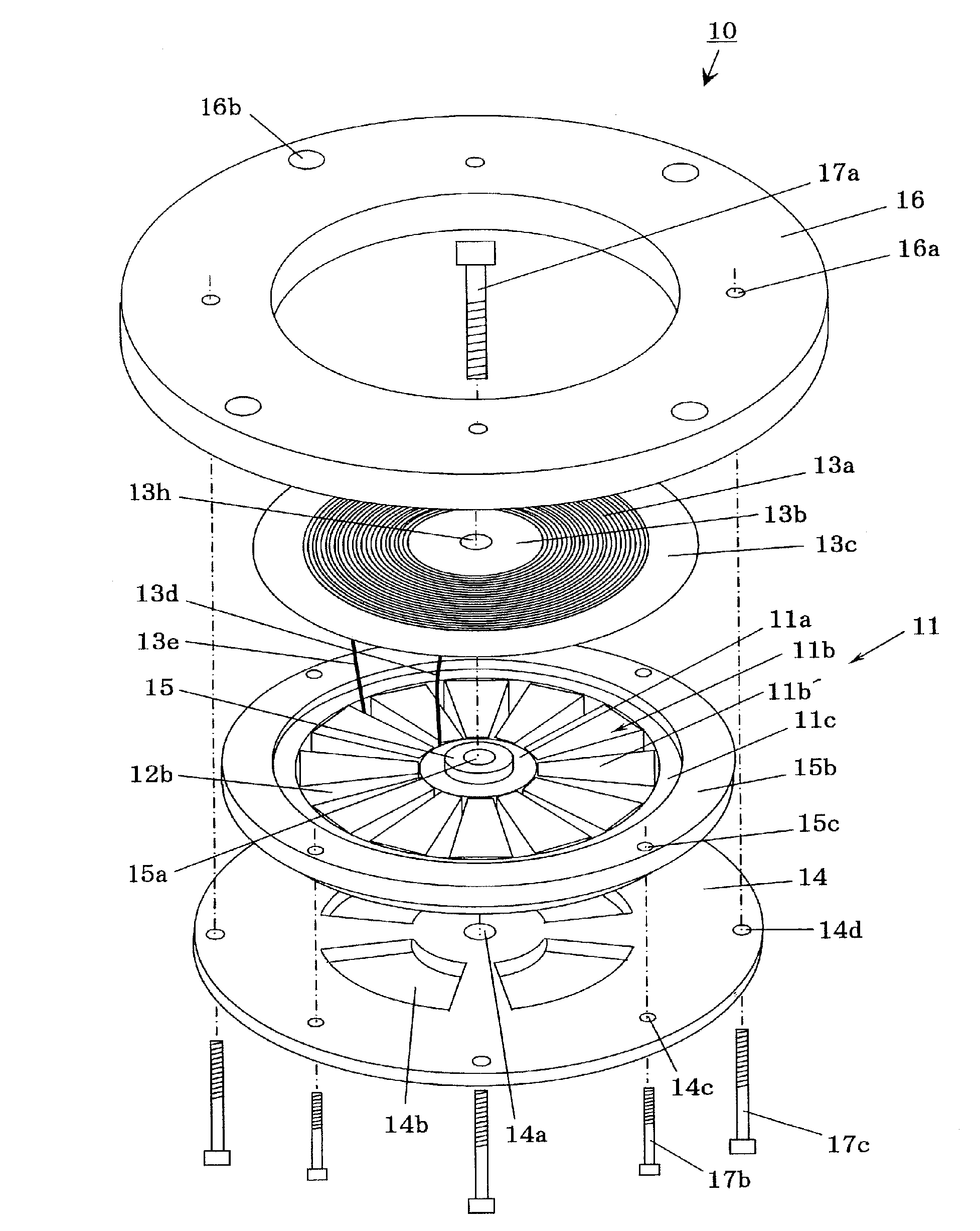
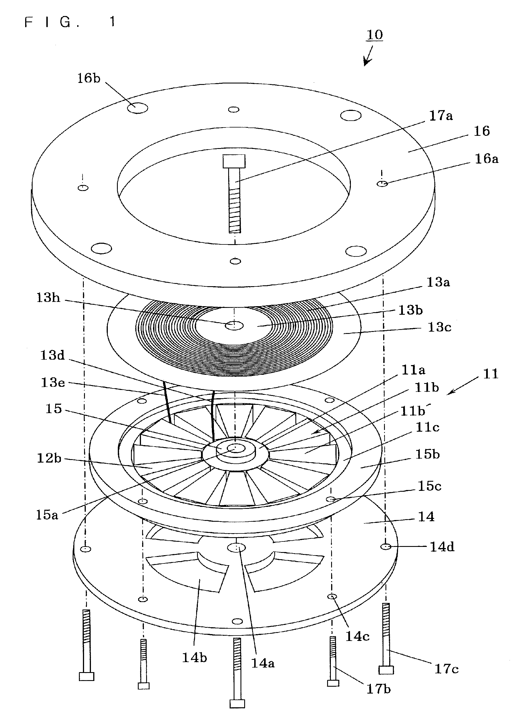
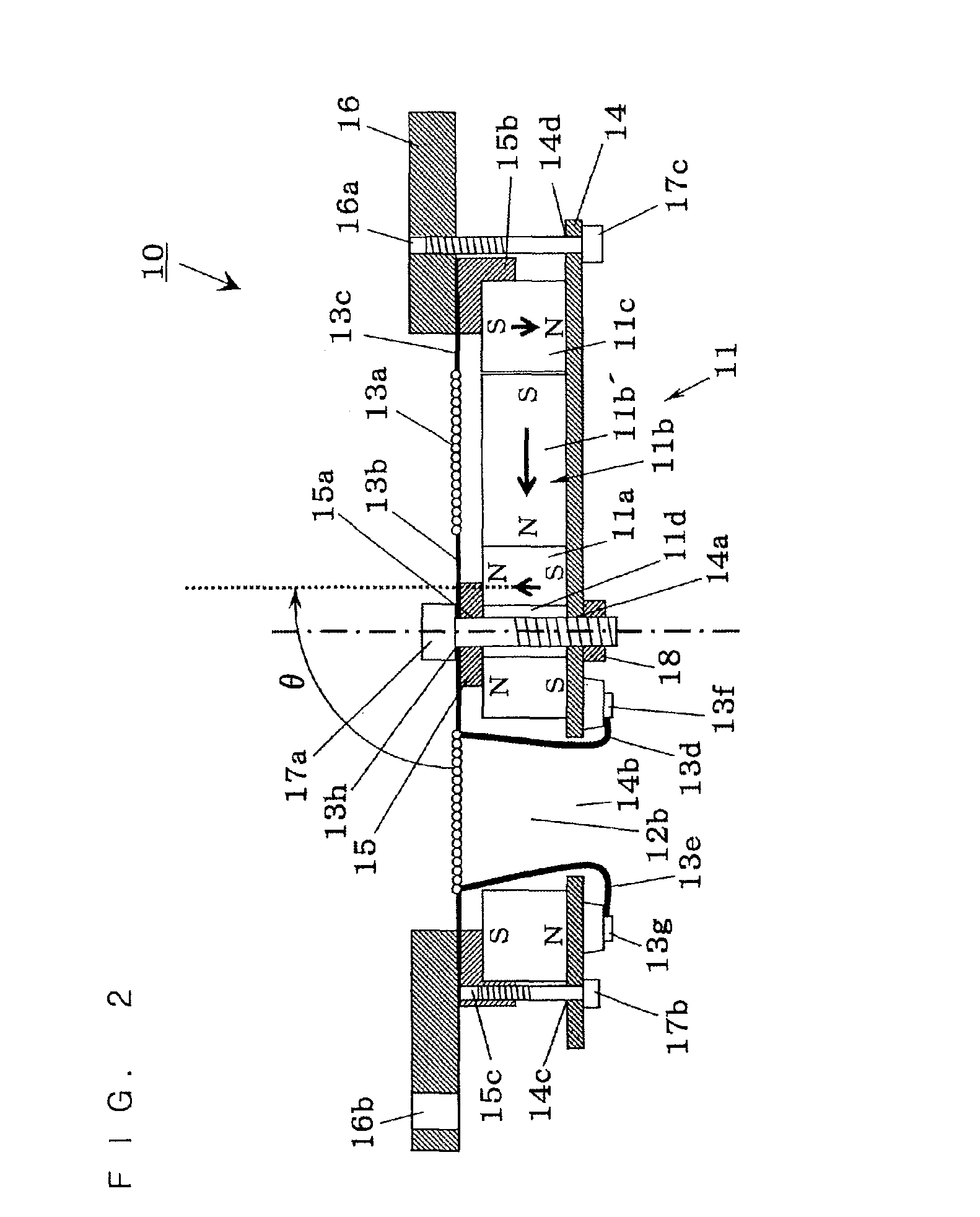
[0153]FIG. 1 is a disassembled perspective view showing an electroacoustic transducer according to Embodiment 1. FIG. 2 is a schematically sectional end view showing the major parts of the electroacoustic transducer according to Embodiment 1.

[0154]In FIG. 1 and FIG. 2, reference numeral 10 denotes an electroacoustic transducer according to Embodiment 1, 11 denotes a magnet plate of the electroacoustic transducer 10 the entirety of which is composed to be roughly disk-shaped, 11a denotes a center area magnet using a ring-shaped neodymium magnet at partial areas of the magnet plate 11, 11b denotes a base area magnet composed of twelve trapezoidal small magnets 11b′ using neodymium magnet at partial areas of the magnet plate 11, 11c denotes an outer circumference area magnet using a ring-shaped neodymium magnet at partial areas of the magnet plate 11, and 11d denotes an insertion hole of a bolt 17a secured at the middle of the center area magnet 11a. Reference numeral 12b denotes twelv...

embodiment 2

[0185]FIG. 3 is a schematically sectional end view showing the major parts of an electroacoustic transducer according to Embodiment 2.

[0186]In FIG. 3, reference numeral 20 denotes an electroacoustic transducer according to Embodiment 2, 21 denotes a magnet plate of the electroacoustic transducer 20 the entirety of which is composed to be disk-shaped, 21a denotes a center area magnet using a ring-shaped neodymium magnet at partial areas of the magnet plate 21, 21b denotes a base area magnet composed of a plurality of trapezoidal small magnets 21b′ using a neodymium magnet at partial areas of the magnet plate 21, 21d denotes a front center area magnet having a semispherical forward portion, which is installed at the front center part of an acoustic diaphragm 23a, is formed to be ring-shaped, and uses a neodymium magnet, and 21e denotes a front outer circumference area magnet that is installed at the front outer circumference portion of the acoustic diaphragm 23a and uses a ring-shaped...

embodiment 3

[0215]FIG. 4 is a schematically sectional end view showing the major parts of an electroacoustic transducer according to Embodiment 3.

[0216]In FIG. 4, reference numeral 30 denotes a composite-type electroacoustic transducer according to Embodiment 3, which is composed by concentrically disposing a high-range electroacoustic transducer 40 and a low-range electroacoustic transducer 50 each of which is independently formed. Reference numeral 41 denotes a magnet plate of a high-range electroacoustic transducer 40, the entirety of which is composed to be disk-shaped, 41a denotes a high-range center area magnet using a ring-shaped neodymium magnet at a partial area of the high-range magnet plate 41, and 41b denotes a high-range base area magnet composed of a plurality of trapezoidal small magnets 41b′ each using a neodymium magnet at a partial area of the high-range magnet plate 41. Reference numeral 42b denotes a high-range sound passage port formed between the trapezoidal small magnets ...


PUM


Abstract

The invention provides an electroacoustic transducer capable of efficiently carrying out conversion from electric signals to sound or from sound to electric signals at low distortion, which requires no special shape nor processing as a magnet, requires no minute setting of the magnetization direction, and sets a distribution of higher magnetic flux densities for effective action with respect to an electric conductor of an acoustic diaphragm than in a magnet plate magnetized in the radius direction although the production process thereof is remarkably simple as in a magnet plate magnetized in the radius direction.

Description

TECHNICAL FIELD[0001]The present invention relates to an electroacoustic transducer that is applied to a speaker, a headphone, an earphone, etc., for converting electric signals into sound, or a microphone and an acoustic wave sensor, etc., for converting received sound into electric signals.BACKGROUND ART[0002]Conventionally, in an electroacoustic transducer called “Gamuzon type speaker,” such a type has been used, in which an acoustic diaphragm on which a flat coil pattern of an electric conductor corresponding to a voice coil is formed is installed at a pair of intermediate parts of a magnetic field generator, and a drive current is supplied to the electric conductor, wherein the acoustic diaphragm is vibrated in the perpendicular direction to the plane thereof.[0003]The acoustic diaphragm of the Gamuzon type speaker is structured so that an electric conductor is disposed almost on the entire surface of the acoustic diaphragm, and is featured in that the entire surface is driven ...

Claims


Application Information

Patent Timeline
Patent Type & Authority Patents(United States)
IPC IPC(8): H04R1/00H04R11/02H04R9/06
CPCH04R7/10H04R7/18H04R9/047H04R9/06H04R9/08
Inventor HANADA, AKITO
Owner HANADA AKITO
Why Eureka
Try Eureka