Electromagnetic contactor

a contactor and electromagnet technology, applied in the direction of contact mechanisms, electromagnetic relay details, contact mechanisms, etc., can solve the problems of reducing the attractive force between the fixed core and the movable plunger, and achieve the effect of increasing the magnetic flux density between the peripheral flange part of the movable plunger and the upper magnetic yoke, improving the attractive force therebetween, and increasing the attractive for

Inactive Publication Date: 2013-12-12
FUJI ELECTRIC FA COMPONENTS & SYST CO LTD
View PDF9 Cites 5 Cited by
  • Summary
  • Abstract
  • Description
  • Claims
  • Application Information

AI Technical Summary

Benefits of technology

[0023]According to this configuration, when the exciting coil is excited in the open state, the magnetic flux density between the peripheral flange part of the movable plunger and the upper magnetic yoke can be increased, improving the attractive force therebetween. Also, in the closed state, attractive force can be generated between the bottom surface of the movable plunger and the bottom plate part of the U-shaped magnetic yoke, generating larger attractive force.
[0024]According to the present invention, when the movable plunger is in the open position and the gap between the bottom surface of the movable plunger and the bottom plate part of the magnetic yoke with a U-shaped cross section is large, a magnetic path that extends through the auxiliary yoke can be formed between the movable plunger and the magnetic yoke with a U-shaped cross section. Consequently, the magnetic flux density between the peripheral flange part of the movable plunger and the upper magnetic yoke can be increased, generating large attractive force therebetween.
[0025]Thereafter, when the bottom part of the movable plunger approaches the bottom plate part of the magnetic yoke with the U-shaped cross section, a magnetic path can be formed directly between the bottom part of the movable plunger and the bottom plate part of the magnetic yoke with the U-shaped cross section, generating attractive force therebetween. As a result, large attractive force combined with the attractive force between the peripheral flange part of the movable plunger and the upper magnetic yoke can be obtained. Therefore, the movable plunger can be retained in the closed state more strongly.

Problems solved by technology

However, there is an unsolved problem that, due to the rising of the movable plunger in this closed state, the magnetic flux density between the movable plunger and the yoke main body drops, reducing the attractive force between the fixed core and the movable plunger.

Method used


Image

  • Electromagnetic contactor
  • Electromagnetic contactor
  • Electromagnetic contactor

Examples


Embodiment Construction

[0040]Embodiments of the present invention are described hereinafter with reference to the drawings.

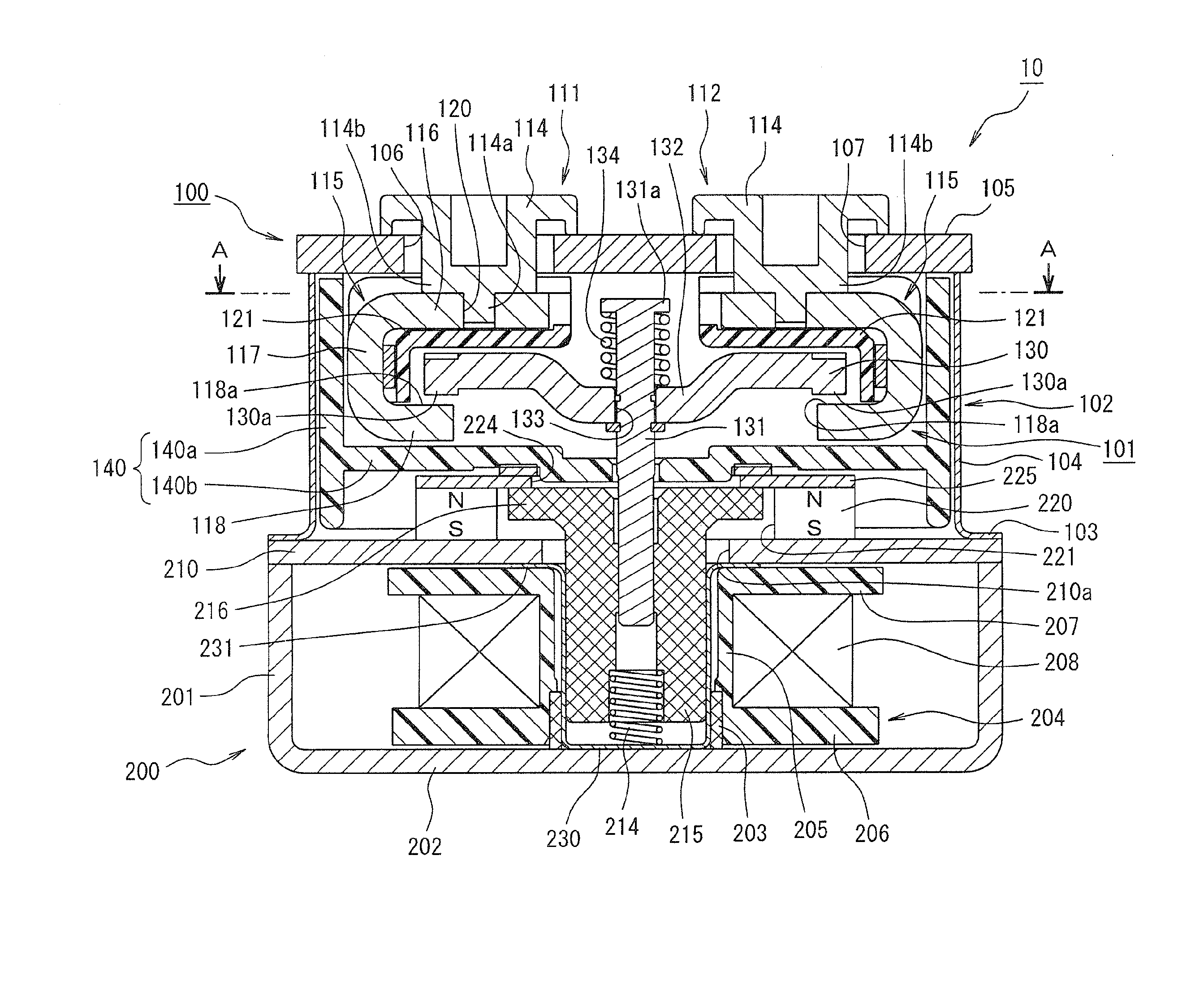
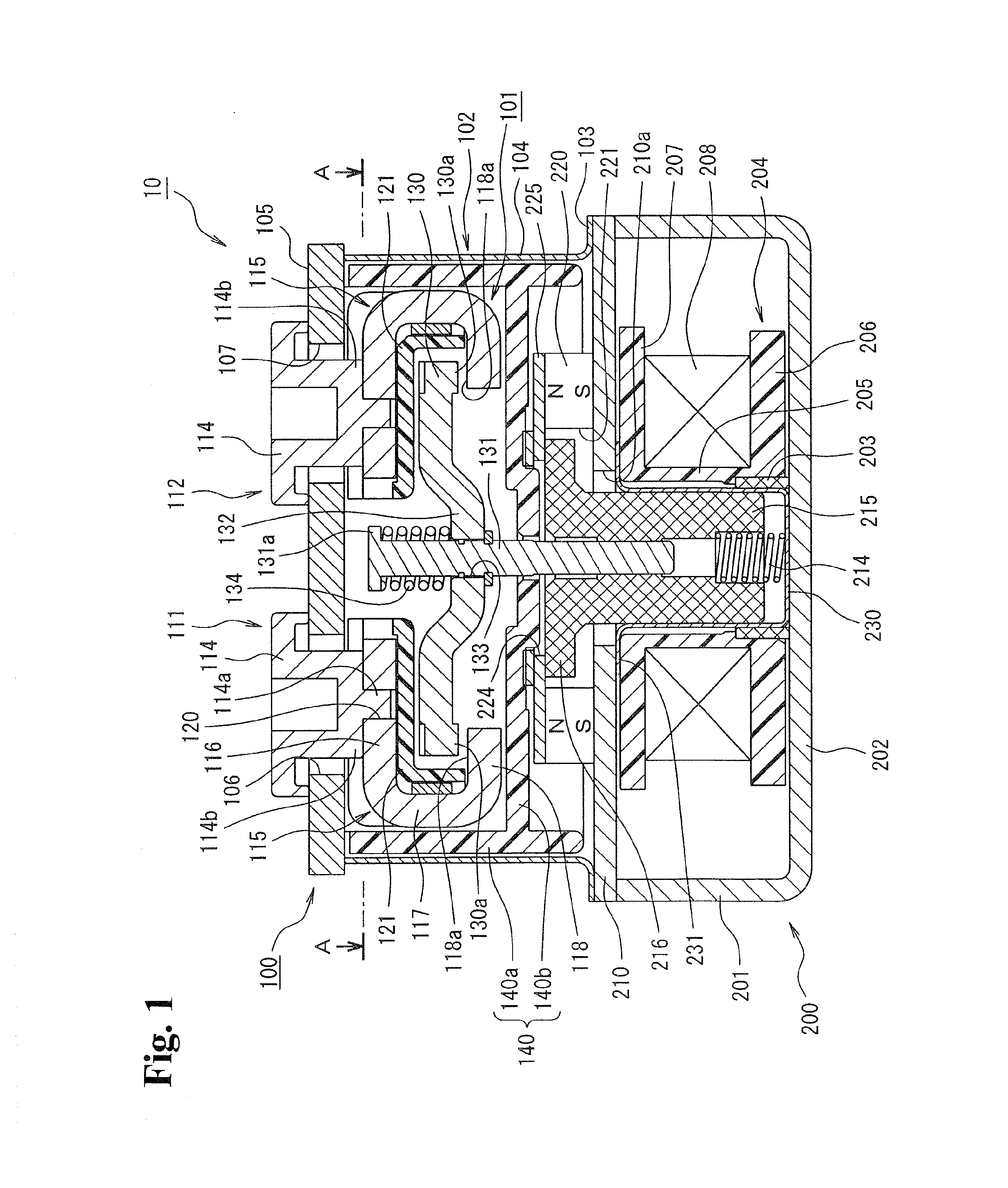
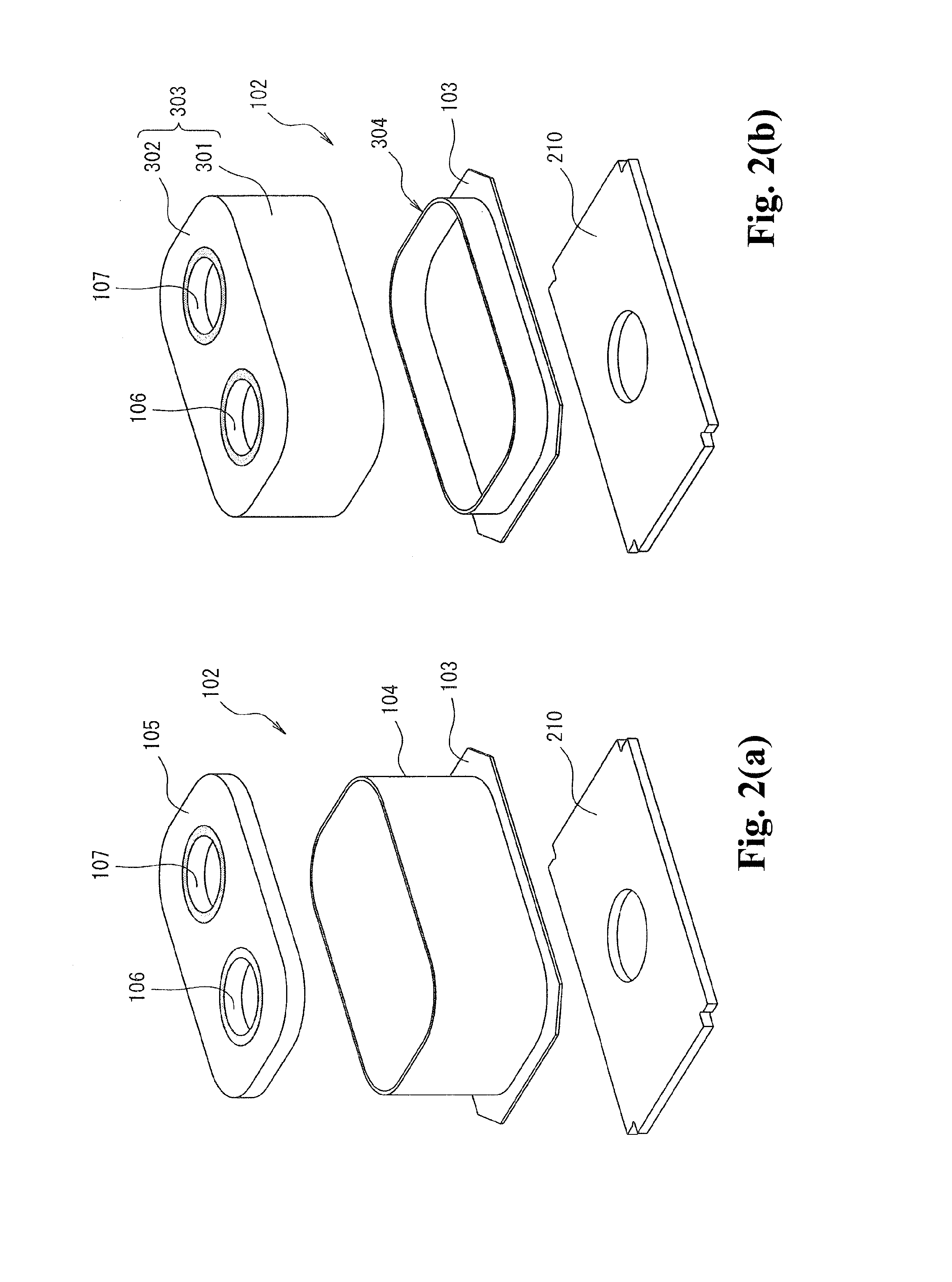
[0041]FIG. 1 is a cross-sectional diagram showing an example of an electromagnetic switch according to the present invention. FIGS. 2(a), 2(b) are exploded perspective views of an arc-extinguishing chamber. Reference numeral 10 shown in FIGS. 1 and 2(a), 2(b) represents an electromagnetic contactor. The electromagnetic contactor 10 is configured of a contact point device 100 in which a contact point mechanism is disposed, and an electromagnetic unit 200 that drives the contact point device 100.

[0042]As it is clear from FIGS. 1 and 2(a), 2(b), the contact point device 100 has an arc-extinguishing chamber 102 for storing a contact point mechanism 101 therein. As shown in FIG. 2(a), this arc-extinguishing chamber 102 has a metallic angular cylindrical body 104 having an outwardly protruding flange part 103 at a metallic lower end part thereof, and a fixed contact point supporting insulat...


PUM


Abstract

An electromagnetic contactor has a pair of fixed contacts; a movable contact disposed to be capable of contacting with and separating from the pair of fixed contacts; and an electromagnetic unit driving the movable contact. The electromagnetic unit has a magnetic yoke having an open upper part; an upper magnetic yoke cross-linked in the open upper part of the magnetic yoke; a spool having a central opening in which an exciting coil is wound around the spool; a movable plunger movably disposed in the central opening of the spool in an axial direction and having a tip end protruding, the movable plunger urged by a return spring; and an auxiliary yoke forming a magnetic path between the movable plunger and the U-shaped magnetic yoke when the movable plunger is in an open position. The movable plunger is coupled to the movable contact through a coupling shaft.

Description

TECHNICAL FIELD[0001]The present invention relates to an electromagnetic contactor having a fixed contact, a movable contact capable of contacting with and separating from the fixed contact, and an electromagnetic unit that drives the movable contact.BACKGROUND ART[0002]An electromagnetic contactor for opening / closing a current path is designed such that a movable contact thereof is driven by an exciting coil and movable plunger of an electromagnetic unit. In other words, while the exciting coil is in a non-excited state, a moving core is urged by a return spring and thereby the movable contact comes to an open state where the movable contact is separated from a pair of fixed contacts disposed at a predetermined interval. By exciting the exciting coil when the movable contact is in the open state, the moving core is attracted to a fixed core and moved against the return spring. As a result, the movable contact contacts the pair of fixed contacts entering a closed state (see Patent D...

Claims


Application Information

Patent Timeline
Patent Type & Authority Applications(United States)
IPC IPC(8): H01H50/58
CPCH01H50/58H01H50/36H01H51/2209H01H50/546H01H2050/025H01H1/54H01H50/42H01H1/20
Inventor NAKA, YASUHIROTAKAYA, KOUETSUSUZUKI, KENJITACHIKAWA, HIROYUKI
Owner FUJI ELECTRIC FA COMPONENTS & SYST CO LTD
Why Eureka
Try Eureka