
Dual coil solenoid valve for a fuel gas control valve and the control method thereof

a technology of solenoid valve and fuel gas, which is applied in the direction of valve operating means/release devices, superconducting magnets/coils, magnetic bodies, etc., can solve the problems of limited energy stored in the battery, accelerated aging of related components on the solenoid valve or even damage, and energy consumption is consumed very quickly, etc., to achieve low power consumption, large attraction force, and small size

Active Publication Date: 2021-06-29
NINGBO RICHEN ELECTRIC APPLIANCE CO LTD
View PDF6 Cites 0 Cited by
  • Summary
  • Abstract
  • Description
  • Claims
  • Application Information

AI Technical Summary

Benefits of technology

The present invention offers a dual coil solenoid valve for fuel gas control valves. This valve requires a small current to generate a large attraction force, making it a low-power, small-size, and simple structure. It can be used with most fuel gas control valves.

Problems solved by technology

However, the solenoid valve of the prior art require a certain number of ampere-turns to produce a large enough attraction force, while owning to the size limitation, it is impossible to make a very large fuel gas control valve; therefore, the solenoid valve can work only when a large current is applied to the coils, and as a result, energy is consumed very quickly, and as the consumed energy is converted into heat energy, the magnet coils easily get hot after they work for a long time, which in turn accelerates the aging of related components on the solenoid valve or even damages them.
In addition, when the solenoid valve is used in a specific environment, for example, in an outdoor environment, where the mains power supply is unavailable or inconvenient and a battery needs to be used as a power supply, the limited energy stored in the battery cannot last long due to the large energy consumption, so the fuel gas control valve has application limitations.

Method used


Image

  • Dual coil solenoid valve for a fuel gas control valve and the control method thereof
  • Dual coil solenoid valve for a fuel gas control valve and the control method thereof
  • Dual coil solenoid valve for a fuel gas control valve and the control method thereof

Examples


embodiment 1

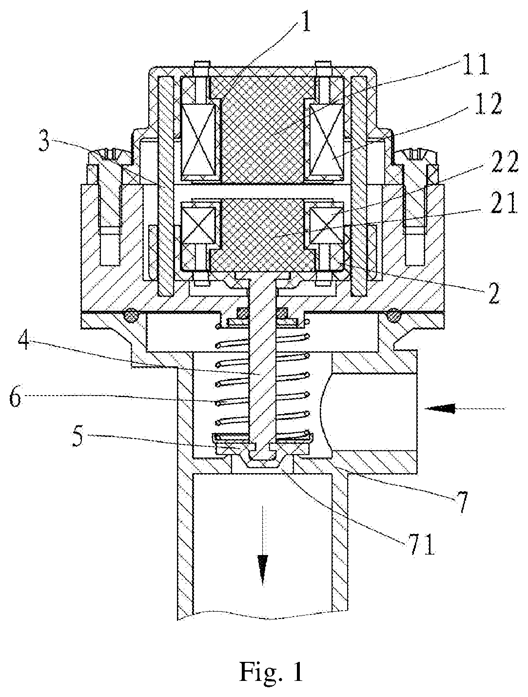
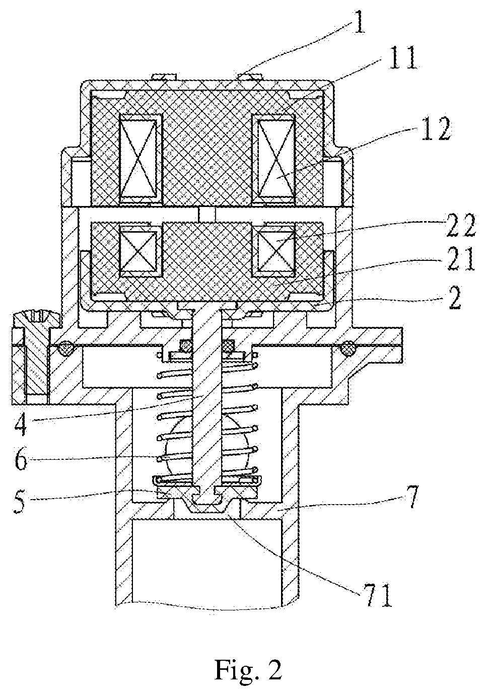
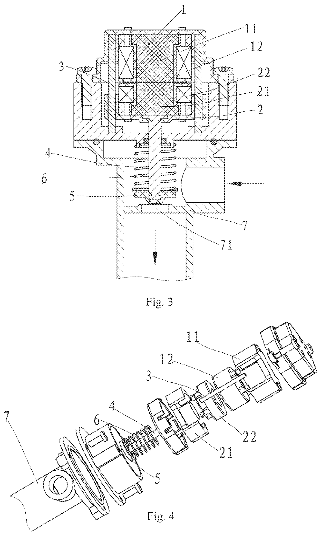
[0037]As shown in FIG. 1 to FIG. 7, a dual coil solenoid valve for s fuel gas control valve comprises a stationary coil assembly 1 and a moving coil assembly 2, said stationary coil assembly 1 comprises a stationary magnetic core 11 and a stationary coil 12, said moving coil assembly 2 comprises a moving magnetic core 21 and a moving coil 22, the materials of said stationary magnetic core 11 and moving magnetic core 21 are both a manganese-zinc ferrite with a high magnetic conductivity, said stationary magnetic core 11 and moving magnetic core 21 are both E-shaped, that is, a notched groove 13 is formed in said stationary magnetic core 11 and said moving magnetic core 21, said stationary coil 12 and moving coil 22 are respectively arranged in the grooves 13 in said stationary magnetic core 11 and moving magnetic core 21, the coils on said stationary coil assembly 1 and moving coil assembly 2 are wound in the same direction according to their installation positions in said dual coil ...

embodiment 2

[0040]As shown in FIG. 8 to FIG. 10, the magnetic core coil of the dual coil solenoid valve for a fuel gas control valve has another structure, wherein said magnetic core is a jug-shaped magnetic core 11′, an annular groove 13′ is provided in the jug-shaped magnetic core, and said jug-shaped magnetic core coil 12′ is arranged in said annular groove 13′.


PUM


Abstract

A dual coil solenoid valve is disclosed for a fuel gas control valve, which comprises a stationary coil assembly and a moving coil assembly, wherein both the stationary coil assembly and the moving coil assembly consist of a magnetic core and a coil. Grooves are provided on the inside of the magnetic cores and coils are arranged in the grooves of the magnetic cores. The stationary coil assembly and the moving coil assembly have an equal cross-sectional area and are arranged oppositely with their axes coinciding with each other. The coils are arranged in the grooves of the magnet cores in such a way that the leakage flux can be reduced and the electromagnetic forces can be increased.

Description

RELATED APPLICATIONS[0001]The present invention is a Nonprovisional Application under 35 USC 111(a), claiming priority to Serial No. CN 201910306166.9, filed on 17 Apr. 2019 and CN 201920515866.4, filed on 17 Apr. 2019, the entirety of both of which are incorporated herein by reference.TECHNICAL FIELD[0002]The present invention relates to a solenoid valve, and in particular to a dual coil solenoid valve for a fuel gas control valve and a control method thereof.BACKGROUND ART[0003]An electromagnet is an electrical device which attracts a ferromagnetic substance and converts an electromagnetic energy into a mechanical energy after being electrified. After an electromagnet is used in a fuel gas control valve to form a solenoid valve, the opening and closing of the fuel gas valve can be realized by turning on and turning off the power of the solenoid valve, and the functions such as alarm and protection can also be realized. There are many types of electromagnets. However, they have the...

Claims


Application Information

Patent Timeline
Patent Type & Authority Patents(United States)
IPC IPC(8): F16K31/06
CPCF16K31/0679F16K31/0655H01F7/066H01F7/1805H01F2007/1692H01F2007/086H01F6/00
Inventor ZHOU, YINWANG, YOUBIN
Owner NINGBO RICHEN ELECTRIC APPLIANCE CO LTD
Learn More