
Friction clutch for transmitting torque

a clutch and friction technology, applied in the field of friction clutches, can solve the problems of inability to make high torque available, inconvenient arrangement of corresponding arrangements, etc., and achieve the effect of eliminating the attraction effect, reliably separated from the rotor, and easy adaptation

Inactive Publication Date: 2012-12-25
LICOS TRUCKTEC
View PDF5 Cites 2 Cited by
  • Summary
  • Abstract
  • Description
  • Claims
  • Application Information

AI Technical Summary

Benefits of technology

The design achieves higher torque transmission by increasing the magnetically effective surface area and attraction force, enabling reliable separation of the friction section from the rotor when energized, thus supporting practical vehicle applications without requiring additional space or costly measures.

Problems solved by technology

Until now, corresponding arrangements have not been suitable for practical purposes, in particular sufficiently high torques cannot be made available.

Method used


Image

  • Friction clutch for transmitting torque
  • Friction clutch for transmitting torque

Examples


Embodiment Construction

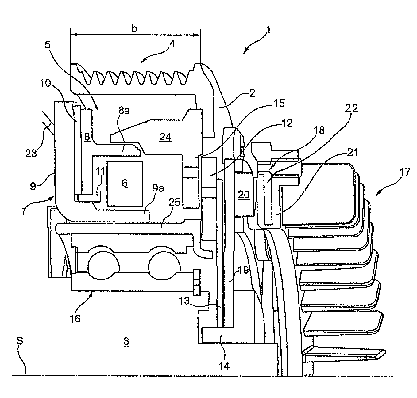
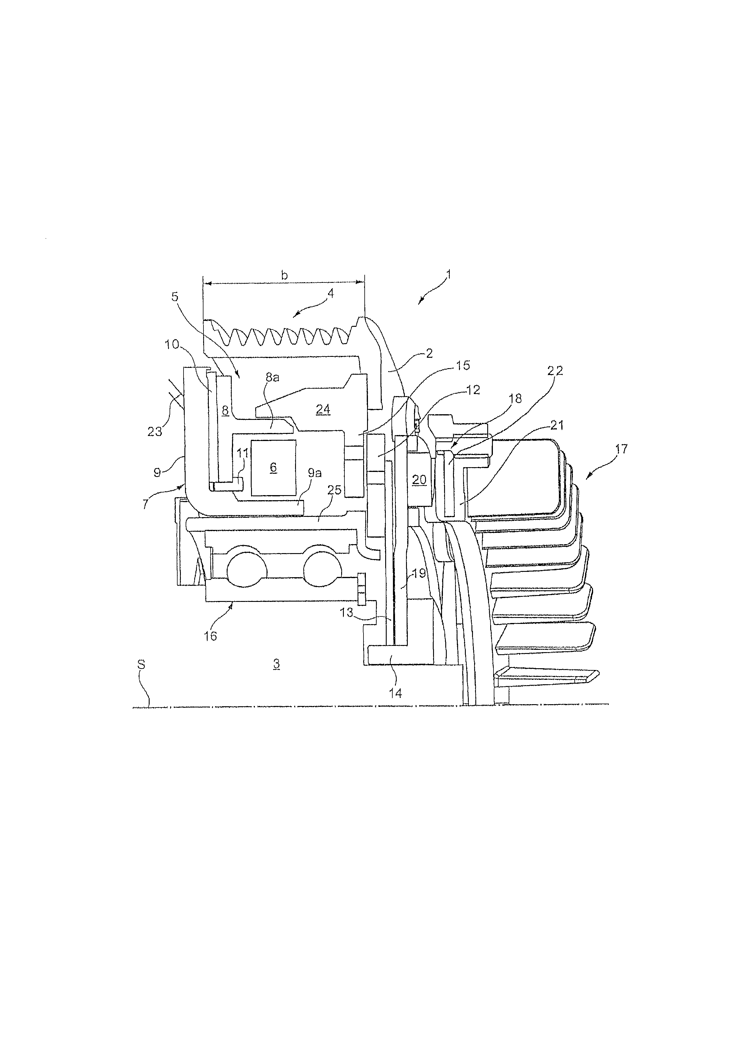
[0021]For this purpose, a friction clutch 1 with a rotationally driven rotor 2 for driving a shaft 3 is provided. The rotor 2 is configured here, for example, as a belt pulley with a belt support 4 for a multiple V belt (not shown). The belt support 4 has an axial extent b with respect to the axis S. An electromagnet arrangement 5 of a failsafe design or with failsafe protection is accommodated radially further inward with respect to the belt support 4. The schematically shown electromagnet arrangement 5 comprises a coil 6, which is surrounded at least partially by magnetically conductive means 7. The magnetically conductive means 7 comprise, according to the figure, a part 8 which is T-shaped in cross section and a part 9 which is L-shaped in cross section. Permanent magnets 10 are accommodated in a radially outwardly directed gap region between the parts 8 and 9. The connection and the cohesion of the T-shaped part 8 and of the L-shaped part 9 can be implemented by means of the pe...


PUM


Abstract

A friction clutch for transmitting torque from a rotor, which can be driven about an axis S, to an element which is to be driven, including a friction disk clutch having an electromagnet arrangement which includes a coil and a magnetically conductive portion including a web section lying radially on the outside with respect to the axis S and a web section lying radially on the inside and oriented axially, and permanent magnets via which an axially movable friction section of the friction disk clutch is magnetically connected to the rotor. When the electromagnetic arrangement is in an electrically switched on state, a bearing of the friction section against the rotor is eliminated by attenuating the magnetic attraction effect of the permanent magnets.

Description

[0001]This application claims the benefit under 35 USC §119(a)-(d) of German Application No. 10 2008 030 165.5 filed Jun. 27, 2008, the entirety of which is incorporated herein by reference.FIELD OF THE INVENTION[0002]The invention relates to a friction clutch for transmitting torque from a rotor to an element which is to be driven.BACKGROUND OF THE INVENTION[0003]Attempts have already been made to improve electromagnetically activated clutches in devices for cooling internal combustion engines, in particular in vehicles, with respect to an emergency operating mode in the case of a functional failure of an electromagnetic part.[0004]In such clutches, for example, electromagnetic arrangements are used which have permanent magnets with which a friction clutch can be activated. By connecting the electromagnetic part into the circuit it is possible to deactivate the effect of the permanent magnets.[0005]Until now, corresponding arrangements have not been suitable for practical purposes,...

Claims


Application Information

Patent Timeline
Patent Type & Authority Patents(United States)
IPC IPC(8): F16D27/01F16D27/112
CPCF16D27/14F16D27/112F04D13/021F04D13/022F04D13/024
Inventor GEIGER, SIGMUND
Owner LICOS TRUCKTEC
Learn More