Valve actuator

a valve actuator and valve body technology, applied in the direction of positive displacement liquid engine, magnet body, piston pump, etc., can solve the problem of slow change in magnetic flux, and achieve the effect of reducing the dependence of magnetic reluctance, reducing the reluctance of respective gaps to penetrate magnetic field lines, and very precise timing of the movement of the movable magnetic componen

Active Publication Date: 2011-10-20
ARTEMIS INTELLIGENT POWER +1
View PDF9 Cites 14 Cited by
  • Summary
  • Abstract
  • Description
  • Claims
  • Application Information

AI Technical Summary

Benefits of technology

[0027]Another possible embodiment can be achieved, if said magnetic flux limiting means, in particular said variable magnetic flux limiting means are arranged solely in said first region of said magnetic core, preferably in the region of said bifurcating branch. This design can prove to be particularly useful, because this way the magnetic flux, particularly the magnetic flux generated by variable magnetic field generating device can be easily confined to the first region of the magnetic core at low magnetic fluxes. If, however, the magnetic flux exceeds the limit, defined by the magnetic flux limiting means, the magnetic flux will then “leave” the first region by virtue of the magnetic flux limiting means, thus entering the second region. This, however, is usually the preferred distribution of the magnetic fluxes over the regions of the magnetic core if the cancellation of the magnetic flux is desired. In particular, this way the cancellation of the magnetic flux generated by the permanent magnetic field generating device and / or the cancellation of the latching force of the movable magnetic component can be particularly efficient and / or the timing of the movement of the movable magnetic component can be very precise. This way, a valve actuator with an advantageous behaviour can be provided.
[0028]It is also possible to design the valve actuator in a way that at least one of said gaps, in particular said first gap and / or said second gap comprises at least one magnetic flux enhancing means and / or at least one magnetic flux density reducing means. Using such a design, the reluctance of the respective gap towards the penetration of magnetic field lines can be reduced. Furthermore, the use of such a design will generally result in a lower dependence of the magnetic reluctance of the respective gap on the size of the gap. This way, the force generated across the respective gap can be more consistent. Such a magnetic flux enhancing means and / or magnetic flux density reducing means can be realized by enlarging and / or aligning the respective surfaces, for example. A possible way to do this is to provide for an inclined “cutting plane” of the gap and / or to provide for cone shaped features on the first surface of the moveable magnetic component and / or on the first surface of the magnetic core, i.e. within the gap.
[0029]It is also possible to provide the valve actuator with at least one mechanical energy storage device, in particular with an elastically deformable device like a spring. This way, kinetic energy of the movable magnetic component and / or external forces (e.g. exerted by hydraulic fluid), acting on the movable magnetic component can be converted into storable energy. This storable energy can be released at a later time during the working cycle of the valve actuator. If the stored energy is released at an appropriate time, it is possible, for example, to decrease the opening and / or closing time of the valve actuator. Furthermore, the stored mechanical energy can be used for decreasing the amount of energy, necessary for driving the valve actuator. Therefore, energy can be conserved.
[0030]Another possible embodiment of the valve actuator can be achieved, if said moveable magnetic component can be at least moved into a first end position, where the first gap is essentially closed, and / or a second end position where the second gap is essentially closed. Particularly in the proposed end positions, the magnetic fluxes usually generate the highest forces. Seen vice-a-versa, a certain force can be produced with a comparatively low magnetic flux. Since the valve actuator usually remains in the end positions most of the time during a working cycle of the valve actuator, the overall energy consumption of the valve actuator can be reduced significantly, if the energy consumption of the valve actuator in one or both end positions is reduced. Therefore, a particularly energy saving valve actuator can be achieved.

Problems solved by technology

However, such a slow change in the magnetic flux is the standard behaviour of typical variable magnetic field generating devices, like electric coils.
However, since the magnetic flux through the secand region of the valve actuator is not (yet) influenced by the magnetic flux generated by the variable magnetic field generating device (as long as the magnetic flux limit of the magnetic flux limiting device is not yet reached), the magnetic flux generated by permanent magnetic flux generating device can hold the movable magnetic component in it's latched position, despite of the external forces acting on the movable magnetic component and the magnetic flux generated by the variable magnetic field generating device.

Method used


Image

  • Valve actuator
  • Valve actuator
  • Valve actuator

Examples


Embodiment Construction

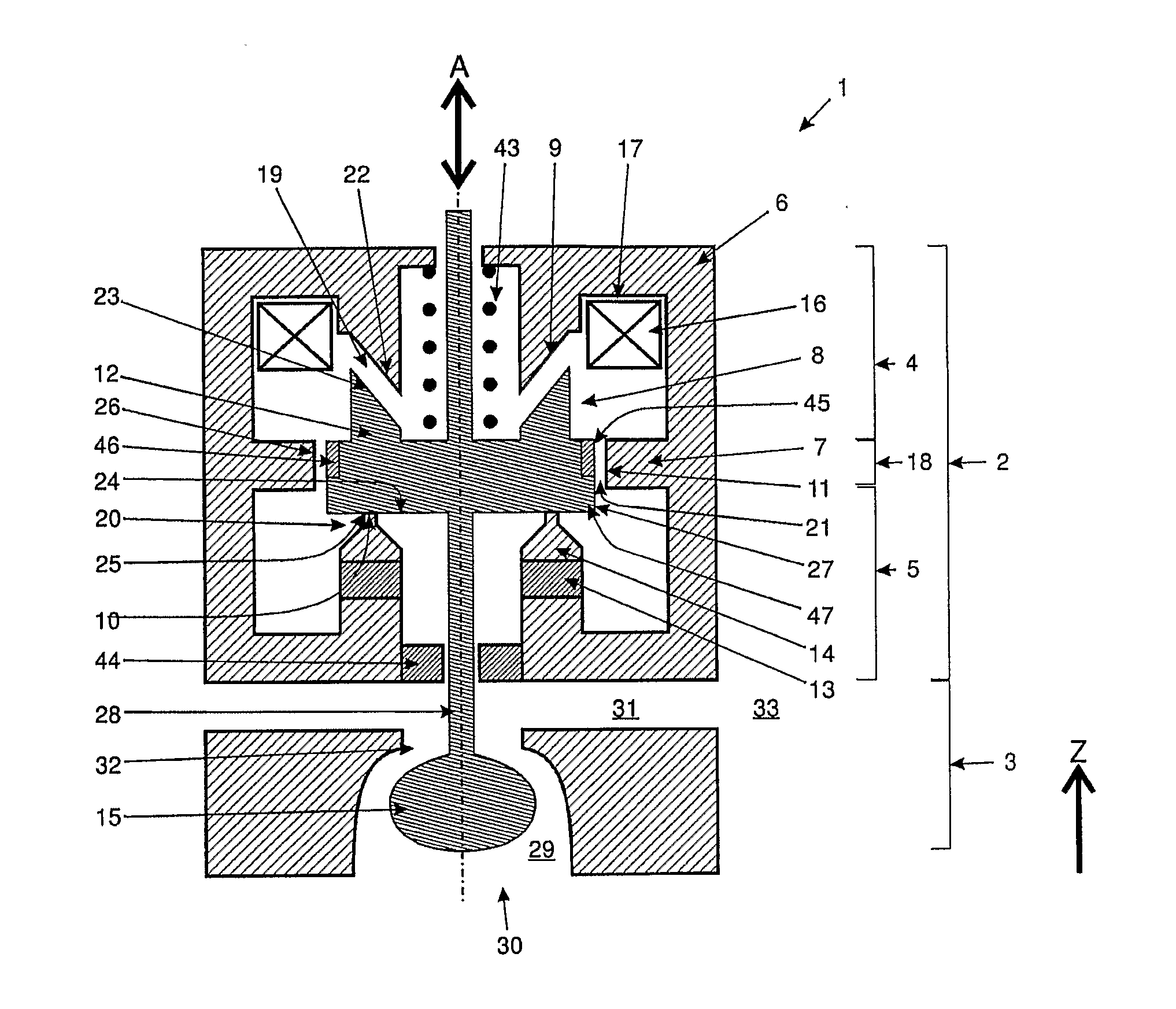
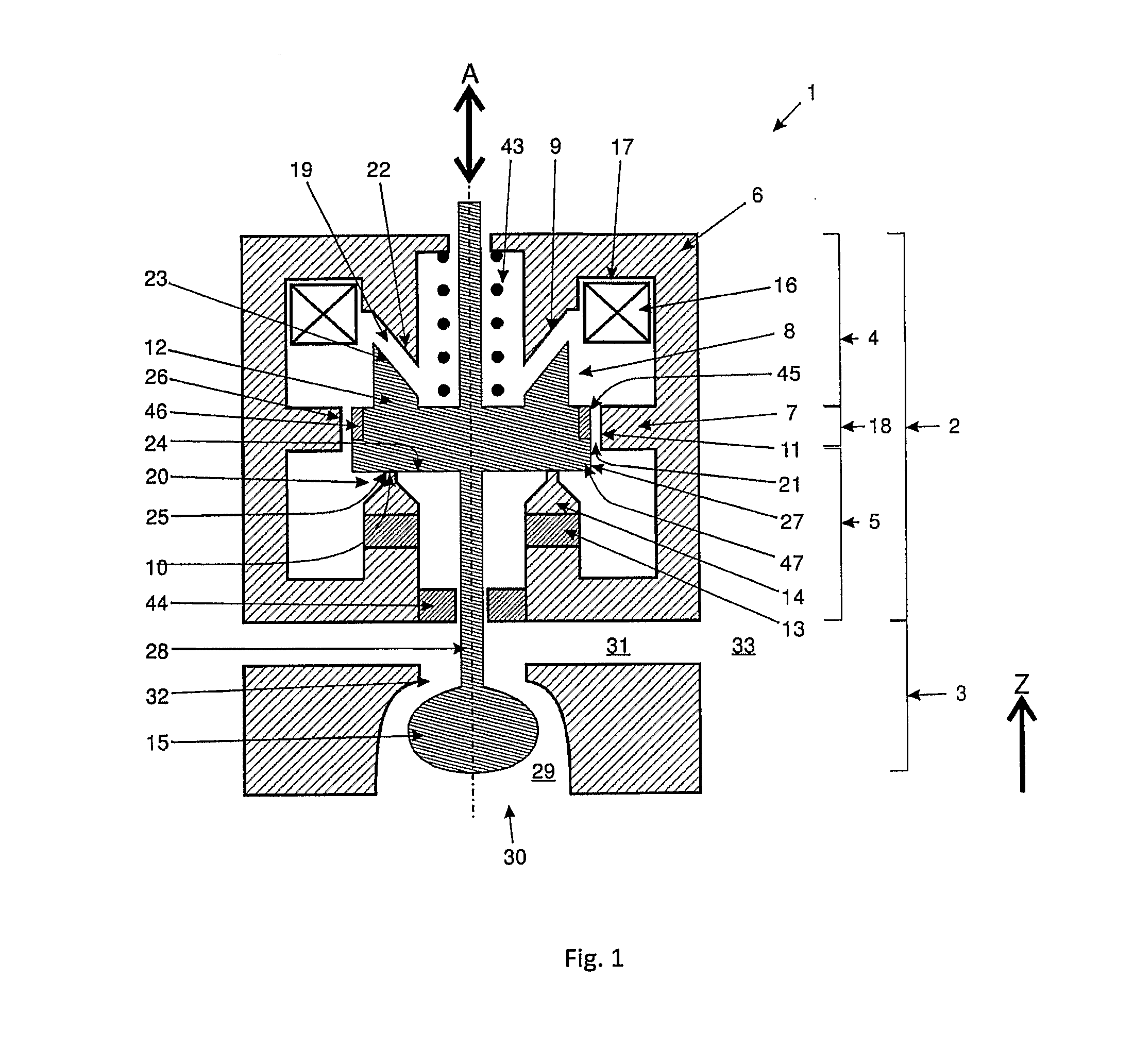
[0046]In FIG. 1, a schematic cross section through a valve unit 1, comprising a valve actuator section 2 and a valve orifice section 3 is shown. The valve unit 1 is essentially rotationally symmetric.

[0047]In the valve actuator section 2 a magnetic core 6 is provided. The magnetic core 6 is essentially made of a soft magnetic material, showing ferromagnetic properties. The magnetic core 6 is provided with a bifurcating web 7, which is circumferentially arranged on the inside of the magnetic core 6. In the embodiment shown in FIG. 1, the bifurcating web 7 lies roughly at half height of the magnetic core 6. The bifurcating web 7 defines an upper portion 4 and a lower portion 5 of the magnetic core 6. Of course, the position of the bifurcating web 7 can be chosen different as well.

[0048]The magnetic core 6 is provided with an interspace 8. The interspace 8 is defined by three neighboring edges 9, 10, 11 of the magnetic core 6. The first edge 9 forms part of the upper portion 4 of the m...


PUM


Abstract

The invention relates to a valve actuator (2), comprising a magnetic core (6) with an interspace (8) and at least one bifurcating branch (7), at least one variable magnetic field generating device (16), at least one permanent magnetic field generating device (13) and at least one movable magnetic component (12), wherein the bifurcating branch (7) defines a first region (4) and a second region (5) of said magnetic core (6). Said movable magnetic component (12) is movably arranged within said interspace (8) of said magnetic core (6) in such a way that a first gap (19) is formed between a first surface (23) of said movable magnetic component (12) and a first surface (22) of said interspace (8) of said magnetic core (6), a second gap (20) is formed between a second surface (24) of said movable magnetic component (12) and a second surface (25) of said interspace (8) of said magnetic core (6), and a third gap (21) is formed between a third surface (27) of said movable magnetic component (12) and a third surface (26) of said bifurcating branch (7) of said magnetic core (6). At least one of said variable magnetic field generating devices (48, 49) is associated with said first region (4) of said magnetic core (6) and at least one of said permanent magnetic field generating devices (13) is associated with said second region (5) of said magnetic core (6). Said valve actuator (2) is designed and arranged in a way that a magnetic flux, generated by at least one at least one of said variable magnetic field generating devices (16) is able to exert a force on said at least one movable magnetic component (12) and is able to cancel the magnetic flux (48, 49), generated by at least one of said permanent magnetic field generating devices (13). At least one magnetic flux limiting means (7, 12) is provided, whose magnetic flux limit can be reached or exceeded.

Description

CROSS REFERENCE TO RELATED APPLICATIONS[0001]This application is entitled to the benefit of and incorporates by reference essential subject matter disclosed in International Patent Application No. PCT / DK2009 / 000226 filed on Oct. 27, 2009 and European Patent Application No. 08018862.6 filed on Oct. 29, 2008.FIELD OF THE INVENTION[0002]The invention relates to a valve actuator, comprising a magnetic core with an interspace and at least one bifurcating branch, at least one variable magnetic field generating device, at least one permanent magnetic field generating device, at least one movable magnetic component and at least one magnetic field intensity limiting means. The invention also relates to an actuated valve, comprising a valve actuator, as well as to a fluid working machine, comprising at least one valve actuator and / or one actuated valve. Furthermore, the invention relates to a method of operating a valve actuator, comprising a magnetic core with an interspace, at least one var...

Claims


Application Information

Patent Timeline
Patent Type & Authority Applications(United States)
IPC IPC(8): F16K31/08
CPCF04B7/0076F04B49/246H01F7/1615H01F7/081H01F7/13F16K31/082F16K31/08H01F7/08H01F7/16
Inventor RAMPEN, WILLIAM HUGH SALVINCALDWELL, NIALL JAMESSTEIN, UWE BERNHARD PASCAL
Owner ARTEMIS INTELLIGENT POWER
Why Eureka
Try Eureka