Iron core for stationary apparatus and stationary apparatus

a stationary apparatus and iron core technology, applied in the direction of electrical apparatus, transformer/inductance details, basic electric elements, etc., can solve the problems of increasing cost and upsizing of iron cores, and achieve the effects of low cost, low loss, and low magnetic flux density

Inactive Publication Date: 2008-11-06
HITACHI IND EQUIP SYST CO LTD
View PDF6 Cites 2 Cited by
  • Summary
  • Abstract
  • Description
  • Claims
  • Application Information

AI Technical Summary

Benefits of technology

[0005]It is generally known that magnetic flux in a magnetic flux distribution inside a wound iron core for a stationary apparatus is mal-distributed toward the inner periphery side where the magnetic path of laminated magnetic steel sheets is short and magnetic resistance is small. Thus, the magnetic flux density becomes higher and iron loss deteriorates on the inner periphery side of the wound iron core where magnetic flux is concentrated, and therefore it is important to make uniform the magnetic flux distribution inside the wound iron core in realizing low loss.
[0007]In order to solve the above described problems, the present invention disposes a magnetic steel sheet having a magnetic characteristic inferior to that on an outer periphery side on an inner periphery side having a shorter magnetic path and smaller magnetic resistance and disposes a magnetic steel sheet having a magnetic characteristic superior to that on the inner periphery side on the outer periphery side having a longer magnetic path and greater magnetic resistance to thereby make uniform the magnetic flux distribution in a sectional area of the iron core, prevent the magnetic flux density on the inner periphery side of the wound iron core from increasing and improve iron loss.
[0011]Furthermore, the stationary apparatus provided with a wound iron core made up of laminated magnetic steel sheets is characterized in that a magnetic steel sheet having a magnetic characteristic inferior to that on the outer periphery side is disposed on the inner periphery side having a shorter magnetic path and smaller magnetic resistance and a magnetic steel sheet having a magnetic characteristic superior to that on the inner periphery side is disposed on the outer periphery side having a longer magnetic path and greater magnetic resistance.

Problems solved by technology

As part of measures against global warming, there is a tendency toward low loss transformers in recent years, and in order to reduce iron loss (non-load loss) generated in an iron core or copper loss (load loss) generated in a coil, the former is designed to increase the amount of magnetic steel sheet used and secure a greater sectional area of the iron core to thereby reduce a magnetic flux density or use an expensive low loss magnetic steel sheet, which leads to upsizing of iron cores and increases in cost.

Method used


Image

  • Iron core for stationary apparatus and stationary apparatus
  • Iron core for stationary apparatus and stationary apparatus
  • Iron core for stationary apparatus and stationary apparatus

Examples


embodiment 1

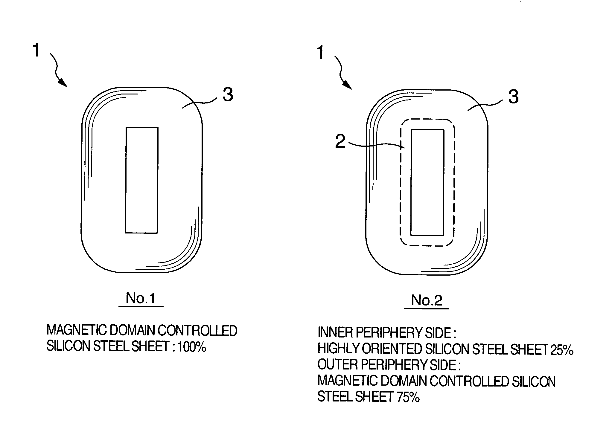
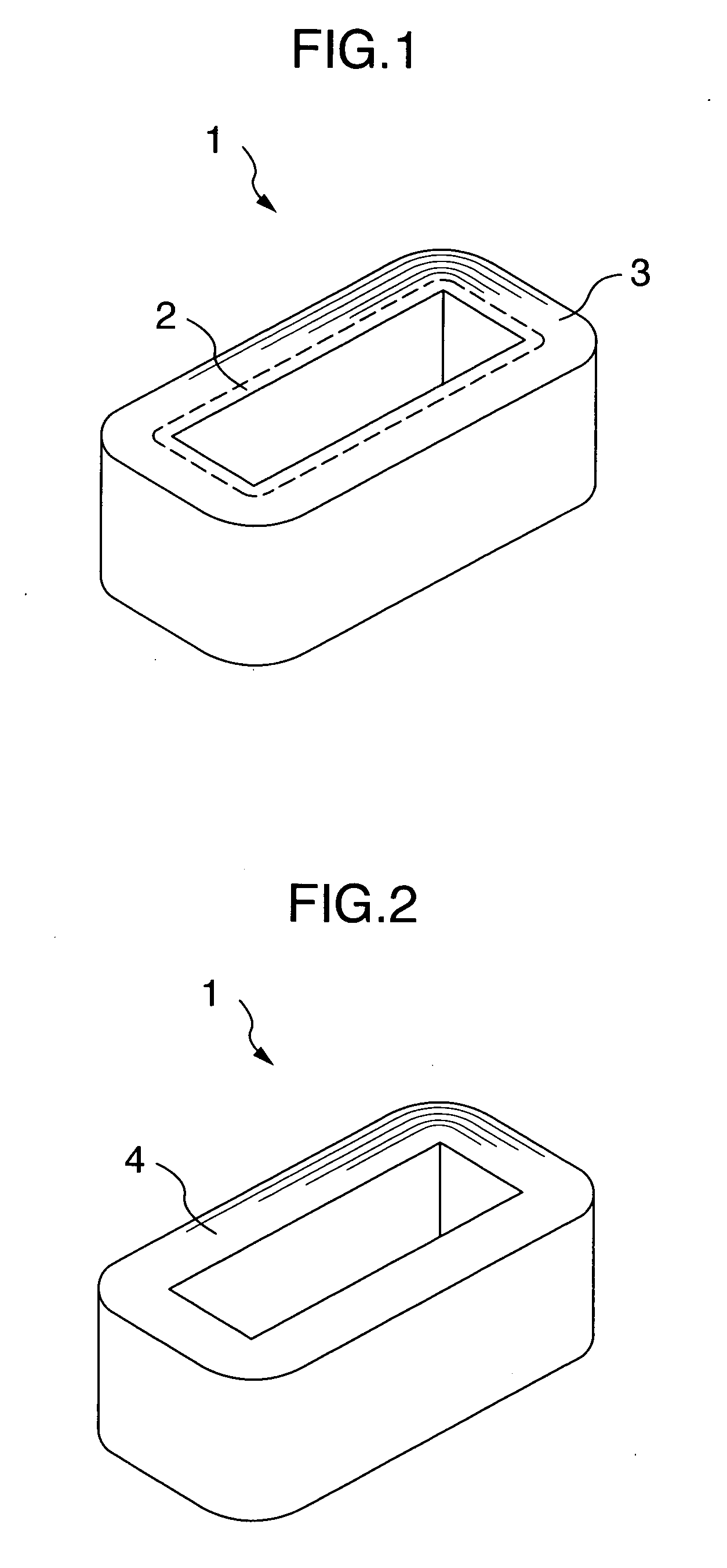
[0029]FIG. 1 shows a wound iron core 1 manufactured using two types of magnetic steel sheets having different magnetic characteristics, which is a wound iron core made up of a highly oriented silicon steel sheet 2 disposed on the inner periphery side of the wound iron core 1 and a magnetic domain controlled silicon steel sheet 3 having a magnetic characteristic superior to that of the highly oriented silicon steel sheet 2 on the outer periphery side. Here, the “highly oriented silicon steel sheet” means a silicon steel sheet in which the rolling direction of the material matches the direction in which magnetic flux passes. The “magnetic domain controlled silicon steel sheet” means a silicon steel sheet made of a highly oriented silicon steel sheet as a raw material, on the surface of which shallow grooves are formed to fragment its magnetic domain and the magnetic characteristic of which is superior to that of the highly oriented silicon steel sheet. With regard to this wound iron c...

embodiment 2

[0034]FIG. 7 shows a three-phase three-leg wound iron core made up of two inner wound iron cores 5a and one outside wound iron core 6a disposed so as to surround the two inner wound iron cores, which is a wound iron core made up of directional silicon steel sheets 7a, 9a disposed on the inner periphery side of each wound iron core and highly oriented silicon steel sheets 8a, 10a having a magnetic characteristic superior to that of the directional silicon steel sheet disposed on the outer periphery side. In the three-phase three-leg wound iron core in FIG. 7, both the inside iron core 5a and outside iron core 6a are disposed such that both lamination thickness ratios of the directional silicon steel sheets 7a, 9a on the inner periphery side of each wound iron core are 25%. Furthermore, with regard to the lamination thickness ratio of the U-leg, V-leg and W-leg as a whole in the three-phase three-leg wound iron core in FIG. 7, the ratio of the directional silicon steel sheet is 25% fo...

embodiment 3

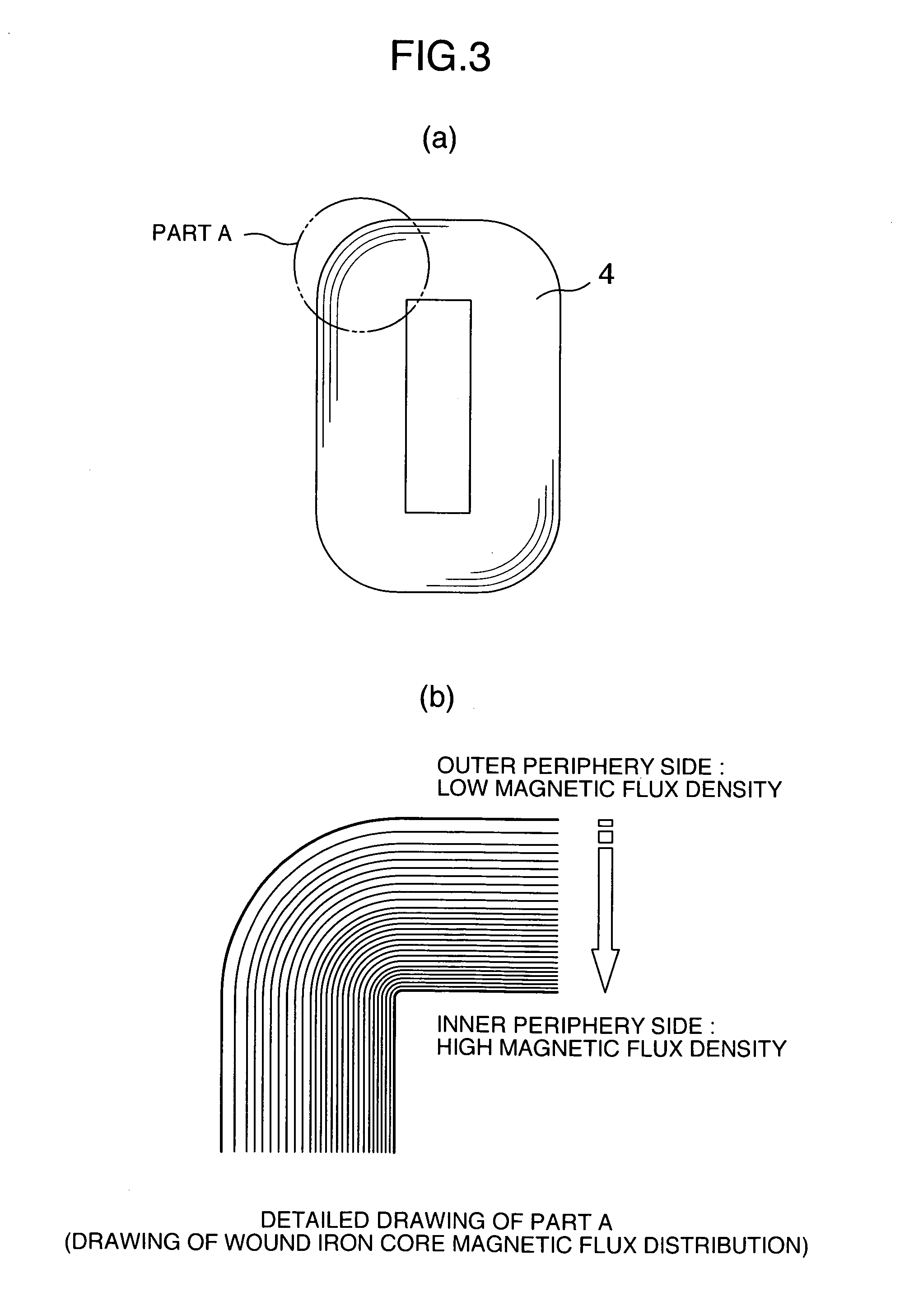
[0039]FIG. 10 shows a stationary apparatus 11 provided with the above described wound iron core, that is, a wound iron core made up of magnetic steel sheets having a magnetic characteristic inferior to that on the outer periphery side disposed on the inner periphery side having a shorter magnetic path and smaller magnetic resistance and magnetic steel sheets having a magnetic characteristic superior to that on the inner periphery side disposed on the outer periphery side having a longer magnetic path and greater magnetic resistance.

[0040]Furthermore, the stationary apparatus 11 provided with an iron core, which is the above described stationary apparatus provided with a wound iron core made up of magnetic steel sheets having a magnetic characteristic inferior to that on the outer periphery side disposed on the inner periphery side having a shorter magnetic path and smaller magnetic resistance so as to account for 40% or less of the total lamination thickness and magnetic steel sheet...


PUM

PropertyMeasurementUnit
magnetic flux densityaaaaaaaaaa
frequencyaaaaaaaaaa
magnetic flux densityaaaaaaaaaa

Abstract

Magnetic flux in a magnetic flux distribution inside a wound iron core for a stationary apparatus is mal-distributed toward the inner periphery side where the magnetic path of a laminated magnetic steel sheet is short with respect to the total lamination thickness and magnetic resistance is small and the inner periphery side on which magnetic flux is concentrated has a high magnetic flux density and increased iron loss, and therefore magnetic steel sheets of different magnetic characteristics are disposed at an arbitrary lamination ratio to make uniform the magnetic flux distribution inside the same wound iron core. In order to make uniform the magnetic flux distribution inside the wound iron core for a stationary apparatus, such a structure is adopted that a magnetic steel sheet having a magnetic characteristic inferior to that on the outer periphery side is disposed on the inner periphery side having a shorter magnetic path and smaller magnetic resistance and a magnetic steel sheet having a magnetic characteristic superior to that on the inner periphery side is disposed on the outer periphery side having a longer magnetic path and greater magnetic resistance to thereby make uniform the magnetic flux distribution in a sectional area of the iron core.

Description

INCORPORATION BY REFERENCE[0001]The present application claims priority from Japanese applications JP2005-199545 filed on Jul. 8, 2005, JP2005-289510 filed on Oct. 3, 2005, the contents of which are hereby incorporated by reference into this application.BACKGROUND OF THE INVENTION[0002]The present invention relates to a wound iron core for a stationary apparatus such as a transformer or reactor, or more particularly, to a wound iron core made up of magnetic steel sheets having a magnetic characteristic (hereinafter refers to iron loss, magnetic permeability) laminated inside the same iron core at an arbitrary distribution ratio of lamination thickness and a stationary apparatus including such a wound iron core.[0003]Magnetic steel sheets of an identical type having an identical magnetic characteristic are laminated inside the same iron core of a wound iron core for a transformer. As part of measures against global warming, there is a tendency toward low loss transformers in recent y...

Claims


Application Information

Patent Timeline
Patent Type & Authority Applications(United States)
IPC IPC(8): H01F27/245
CPCH01F3/04H01F27/25H01F2003/106
Inventor ENDOU, HIROYUKISHINOHARA, MAKOTOKUWABARA, MASANAOAMAKO, YOICHISHIRAHATA, TOSHIKI
Owner HITACHI IND EQUIP SYST CO LTD
Why Eureka
Try Eureka