
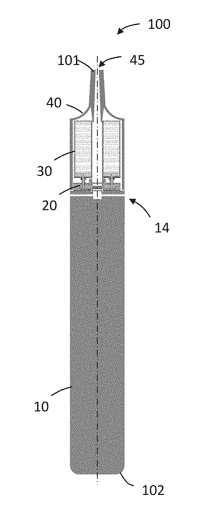
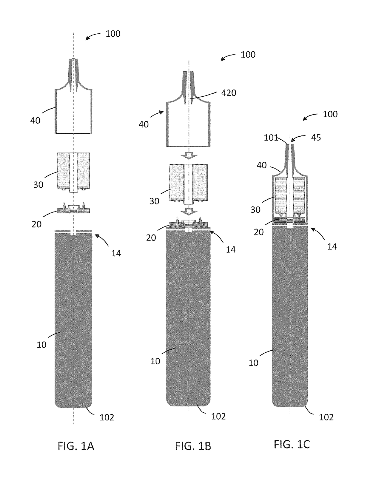
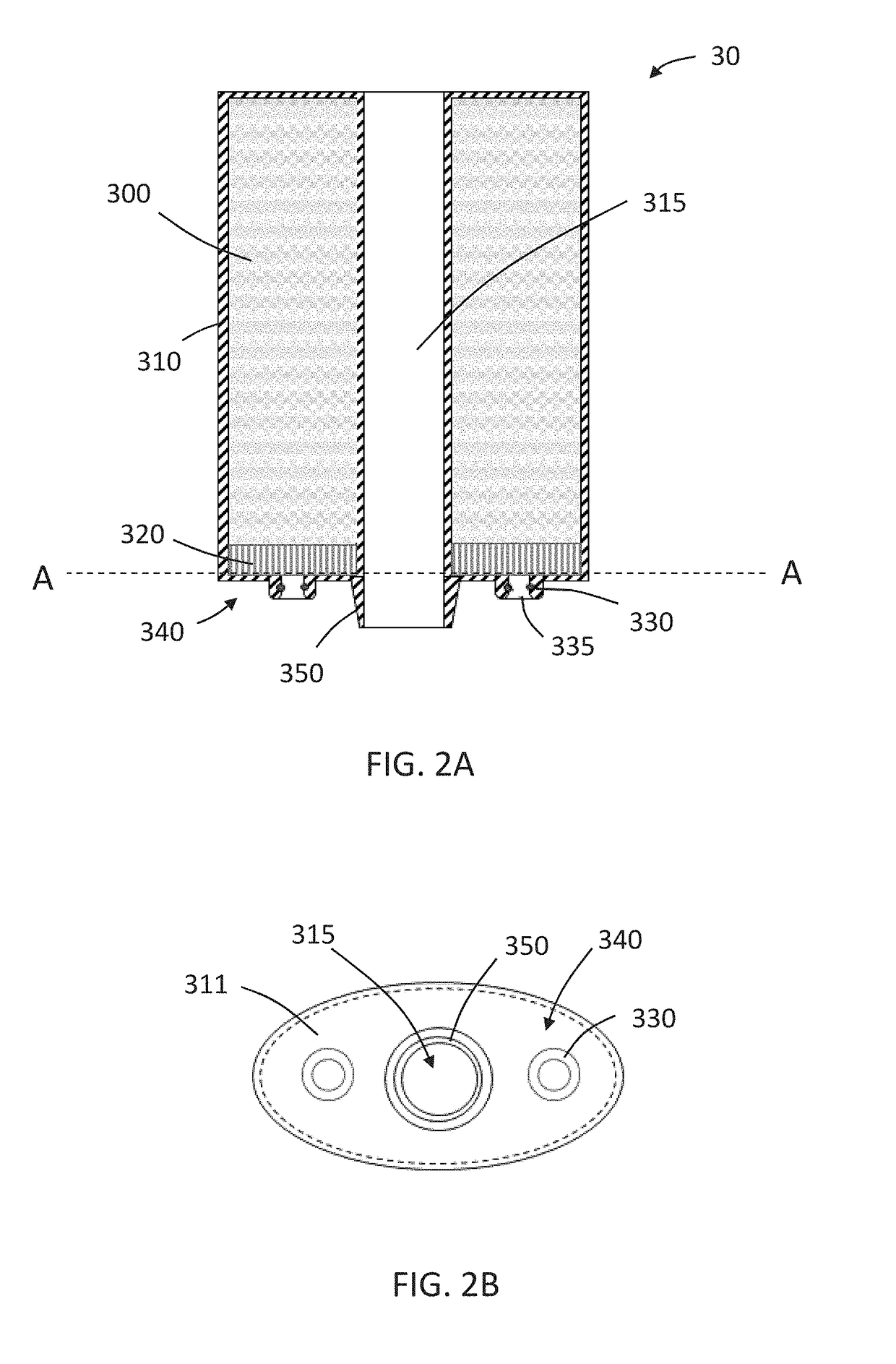
Aerosol-generating system with separate capsule and vaporizing unit

Active Publication Date: 2017-10-05
AKRIA CLIENT SERVICES LLC
View PDF19 Cites 7 Cited by
  • Summary
  • Abstract
  • Description
  • Claims
  • Application Information

AI Technical Summary

Benefits of technology

This patent is about a new kind of aerosol-generating substrate-containing capsule that can be used in a vaporizing unit. The capsule has a separate cover that can be easily attached, which makes it easier and less expensive to manufacture. The capsule has a first mating end that connects to the vaporizing unit, and a second mating end that also connects to the vaporizing unit, making sure that it is secure and can be easily replaced. The vaporizing unit has a sheath that prevents the liquid transfer element from coming into contact with the adult vaper during replacement of the capsule. The sheath is biased in an extended configuration and can be easily retracted to a position that allows the liquid transfer element to be placed in fluidic communication with the aerosol-generating substrate. The patent text also mentions a new type of elongate member and valve interaction that helps to open the valve and allow the liquid transfer element to extend. These features make the vaporizing unit more convenient and user-friendly.

Problems solved by technology

However, cartridges having this arrangement may be relatively expensive to produce.
In part, this is because of the cost of manufacturing the vaporizer assembly.
Application of an electric current to the heating element results in heating due to the resistive nature of the element.

Method used


Image

  • Aerosol-generating system with separate capsule and vaporizing unit
  • Aerosol-generating system with separate capsule and vaporizing unit
  • Aerosol-generating system with separate capsule and vaporizing unit

Examples


Embodiment Construction

[0069]It should be understood that when an element or layer is referred to as being “on,”“connected to,”“coupled to,” or “covering” another element or layer, it may be directly on, connected to, coupled to, or covering the other element or layer or intervening elements or layers may be present. In contrast, when an element is referred to as being “directly on,”“directly connected to,” or “directly coupled to” another element or layer, there are no intervening elements or layers present. Like numbers refer to like elements throughout the specification. As used herein, the term “and / or” includes any and all combinations of one or more of the associated listed items.

[0070]It should be understood that, although the terms first, second, third, etc. may be used herein to describe various elements, components, regions, layers and / or sections, these elements, components, regions, layers, and / or sections should not be limited by these terms. These terms are only used to distinguish one eleme...


PUM


Abstract

An aerosol-generating system may comprise a releasably connectable capsule and vaporizing unit. The capsule may comprise a reservoir for containing an aerosol-generating substrate, an opening in fluidic communication with the reservoir, and a valve configured to control a flow of the aerosol-generating substrate from the reservoir through the opening. The valve may comprise one or more resilient closing members biased towards a closed position. The vaporizing unit may comprise a transfer element and a heating element disposed in a housing. The heating element is configured to heat the aerosol-generating substrate in the transfer element. The vaporizing unit may also comprise an elongate element configured to engage with the valve to deflect the one or more resilient closing members from the closed position to an open position so as place the transfer element in fluidic connection with the reservoir when the capsule is connected to the vaporizing unit.

Description

CROSS-REFERENCE TO RELATED APPLICATIONS[0001]This is a continuation of and claims priority to PCT / EP2017 / 054418, filed on Feb. 24, 2017, and further claims priority to EP 16163362.3, filed on Mar. 31, 2016, both of which are hereby incorporated by reference in their entirety.BACKGROUNDField[0002]This disclosure relates to multi-part electrically heated aerosol-generating systems and associated devices, articles, and methods.Description of Related Art[0003]One type of aerosol-generating system is an electrically operated handheld aerosol-generating system. Known handheld electrically operated aerosol-generating systems include a device portion comprising a battery and control electronics, a replaceable cartridge portion comprising a supply of aerosol-generating substrate, and an electrically operated vaporizer. A cartridge comprising both a supply of aerosol-generating substrate and a vaporizer is sometimes referred to as a “cartomizer”. The vaporizer typically includes a coil of hea...

Claims


Application Information

Patent Timeline
IPC IPC(8): A24F47/00H05B1/02A24F40/10A24F40/485
CPCA24F47/008H05B2203/021H05B1/0244H05B3/04H05B3/44H05B2203/014H05B2203/022A24F40/10A24F40/485A24F40/42
Inventor FORCE, ERIC
Owner AKRIA CLIENT SERVICES LLC
Learn More