A wind turbine blade, and a method of reinforcing a wind turbine blade

Inactive Publication Date: 2017-10-05
BLADENA
View PDF10 Cites 0 Cited by
  • Summary
  • Abstract
  • Description
  • Claims
  • Application Information

AI Technical Summary

Benefits of technology

[0008]On this background it is the purpose of the present invention to provide a wind turbine blade with reinforcing devices further reducing the risk of fatigue failure of the rear edge or the girder and/or fatigue failure of the shell and/or fatigue failure in the connection be

Problems solved by technology

This deformation induces peeling stresses in the trailing edge of the blade and consequently this can lead to a fatigue failure in the adhesive joint of the trailing edge where the two shell parts are connected to each other.
Furthermore, the deformation of the of the shel

Method used


Image

  • A wind turbine blade, and a method of reinforcing a wind turbine blade
  • A wind turbine blade, and a method of reinforcing a wind turbine blade

Examples


Embodiment Construction

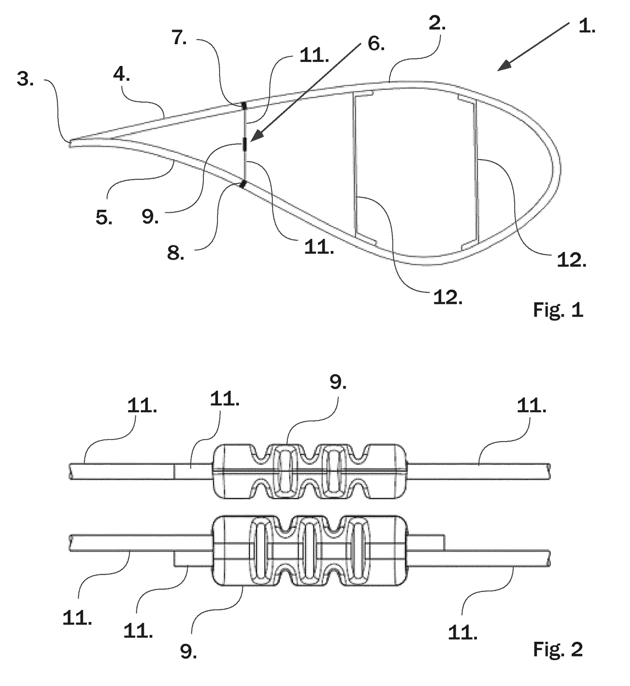
[0025]FIG. 1 shows a cross section of a wind turbine blade (1) with a shell (2) being equipped with an elongated reinforcing member (6) according to the invention.

[0026]The wind turbine blade has a shell (2) with a first shell part (4) and a second shell part (5) being interconnected along the trailing edge (3) of the wind turbine blade (1), and extending in mutually divergent directions from the trailing edge (3).

[0027]Internally in the shell (2) and between the first shell part (4) and the second shell part (5) an elongated reinforcing member (6) is arranged for reducing variations of the distance between the first shell part (4) and the second shell part (5) which may e.g. cause peeling stresses in the trailing edge of the blade and consequently leading to a fatigue failure in the adhesive joint of the trailing edge where the two shell parts (4, 5) are connected to each other.

[0028]In the embodiment shown on FIG. 1 the wind turbine blade further comprise a set (two) of girders (1...


PUM


Abstract

A wind turbine blade comprising a shell having a section with an aerodynamic profile with a trailing part comprising a trailing edge formed by a first shell part and a second shell part both extending from the trailing edge in mutual divergent directions, and where at least one elongated reinforcing member is connected inside the shell for increasing the strength of the blade, each of the at least one elongated reinforcing member having a first end and a second end and extending in a longitudinal direction between the first end being connected to the first part of the shell, and the second end being connected to the second part of the shell and thereby preventing deformation of the trailing part of the shell, and wherein the elongated reinforcing member comprises an elongated element extending in its longitudinal direction between the first and the second end of the elongated reinforcing member, and where at least one end of the elongated element is connected to an overload protection device, being adapted for ensuring that the tension and/or compression on the elongated element does not exceed a certain level.

Description

PRIOR ART[0001]The present invention relates to a reinforced blade for a wind turbine, particularly to a blade comprising a shell having a section with an aerodynamic profile with a trailing part comprising a trailing edge formed by a first shell part and a second shell part both extending from the trailing edge in mutual divergent directions, and where at least one elongated reinforcing member is connected inside the shell for increasing the strength of the blade, each of the at least one elongated reinforcing member having a first end and a second end and extending in a longitudinal direction between the first end being connected to the first part of the shell, and the second end being connected to the second part of the shell and thereby preventing deformation of the trailing part of the shell, and wherein the elongated reinforcing member comprises an elongated element extending in its longitudinal direction between the first and the second end of the elongated reinforcing member...

Claims


Application Information

Patent Timeline
IPC IPC(8): F03D1/06
CPCF05B2260/30F03D1/0675Y02E10/72
Inventor JENSEN, FIND MOLHOLTMEJLSTRUP, RYAN
Owner BLADENA
Why Eureka
Try Eureka