
Wear Test Device and Method

a technology of wear testing and wear, applied in the direction of material analysis, error detection/correction, instruments, etc., can solve the problems of upper rubber cover being subject to impact, and upper rubber cover being subject to wear

Inactive Publication Date: 2017-10-05
YOKOHAMA RUBBER CO LTD
View PDF2 Cites 4 Cited by
  • Summary
  • Abstract
  • Description
  • Claims
  • Application Information

AI Technical Summary

Benefits of technology

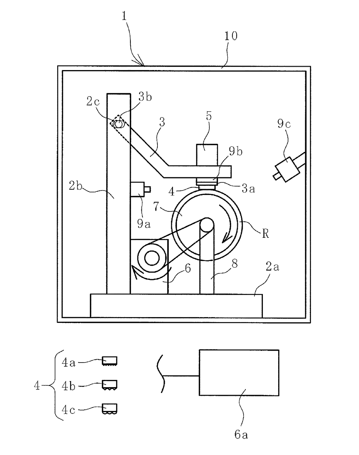
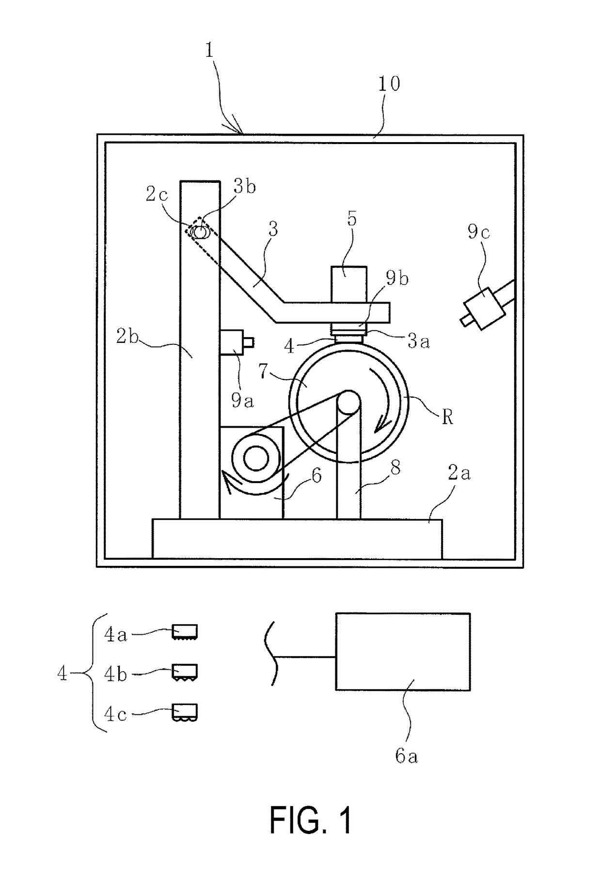
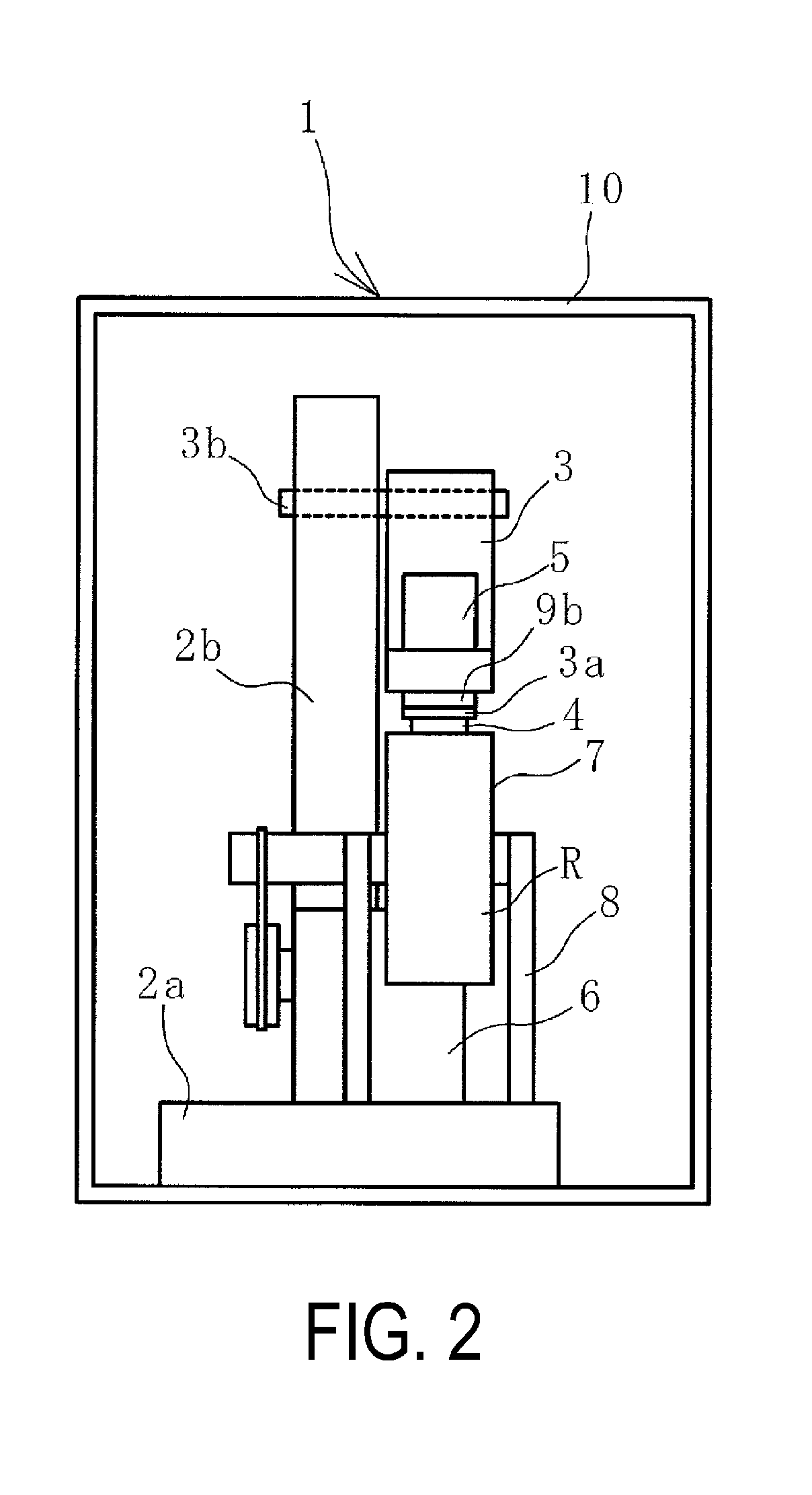
The patent describes a device that can simulate the conditions in which rubber is used in a conveyor belt to determine its wear resistance. The device allows for the speed of the rotating drum and the pressure applied by the contact member to be adjusted, and the contact member can be pressed against the rubber surface in the same way it would be in the conveyor belt. The device also includes a mechanism to change the temperature of the rubber sample, which helps to further mimic the actual use environment. The device can accurately estimate the wear resistance of the rubber sample, even with the most demanding of use environments. Additionally, the device can measure changes in surface temperature during evaluation, providing valuable information on energy generation during wear.

Problems solved by technology

When the objects to be conveyed are fed onto the upper rubber cover of the conveyor belt, the upper rubber cover is subject to impact, and when the surfaces of the objects to be conveyed are sharp, the upper rubber cover sometimes sustains cut damage.
When the objects to be conveyed are loaded on the upper rubber cover and conveyed, the upper rubber cover is subject to wear as a result of the objects to be conveyed sliding on the upper rubber cover.
Thus, they cannot be set for conditions that conform to various environments in which the conveyor belt is used and are inadequate in estimating with high accuracy wear resistance of the upper cover rubber of the conveyor belt should the conveyor belt actually be used.

Method used


Image

  • Wear Test Device and Method
  • Wear Test Device and Method
  • Wear Test Device and Method

Examples


Embodiment Construction

[0020]A wear testing device and method of embodiments of the present technology will be described below with reference to embodiments illustrated in the drawings.

[0021]In a functioning conveyor belt line, as illustrated in FIGS. 3 and 4, objects to be conveyed S conveyed by another conveyor belt 17 is fed onto a conveyor belt 11 and conveyed to a conveying destination by the conveyor belt 11. The objects to be conveyed S may be fed onto the conveyor belt 11 by a hopper and the like. The conveyor belt 11 is mounted between pulleys 15a and 15b at a prescribed tension.

[0022]The conveyor belt 11 is constituted by a core layer 12 including a core made of canvas, steel cord, or the like, and an upper cover rubber 13 and a lower cover rubber 14 that sandwich the core layer 12 therebetween. The core layer 12 is a member that bears the tension that causes the conveyor belt 11 to be stretched. The lower rubber cover 14 is supported by support rollers 16 on a carrier side of the conveyor belt ...


PUM

PropertyMeasurementUnit
rotational speedaaaaaaaaaa
weightaaaaaaaaaa
displacementaaaaaaaaaa

Abstract

A wear testing method includes setting a rotational speed of a rotary drum with a rubber sample attached to an outer surface thereof to a desired speed; setting a pressing load imparted by a contact member to a desired pressing load via a weight member; selecting as the contact member a desired contact member from a plurality of contact members with varying specifications for a contact surface that comes into contact with the surface of the rubber sample; attaching an arm portion that composes a pressing mechanism; rotating the rotary drum; and pressing the contact member against the surface of the rubber sample with the contact member being moveable in a tangent line direction of a rotation direction of the rotary drum, and detecting an amount of displacement in a pressing direction of the contact member pressing against the surface of the rubber sample via a displacement sensor.

Description

TECHNICAL FIELD[0001]The present technology relates to a wear testing device and method, and particularly relates to a wear testing device and method capable of estimating with high accuracy wear resistance of an upper cover rubber of a conveyor belt should the conveyor belt actually be used.BACKGROUND ART[0002]Various objects, including mineral resources such as iron ore and limestone, are conveyed by a conveyor belt. When the objects are conveyed by the conveyor belt, the objects to be conveyed are fed onto an upper rubber cover of the conveyor belt from a hopper or another conveyor belt. The fed objects to be conveyed are carried on the upper rubber cover and conveyed in a traveling direction of the conveyor belt. When the objects to be conveyed are fed onto the upper rubber cover of the conveyor belt, the upper rubber cover is subject to impact, and when the surfaces of the objects to be conveyed are sharp, the upper rubber cover sometimes sustains cut damage. When the objects t...

Claims


Application Information

Patent Timeline
Patent Type & Authority Applications(United States)
IPC IPC(8): G01N3/56G01N33/44G06F11/00G01N33/36
CPCG01N3/56G01N33/36G01N33/00G06F11/006G01N3/00G01N33/445G01N2203/0266G01N2203/0294
Inventor HOU, GANG
Owner YOKOHAMA RUBBER CO LTD
Features
  • Generate Ideas
  • Intellectual Property
  • Life Sciences
  • Materials
  • Tech Scout
  • Unparalleled Data Quality
  • Higher Quality Content
  • 60% Fewer Hallucinations
Learn More