Rapid determination of a relaxation time

a relaxation time and rapid technology, applied in the field of rapid determination of relaxation time, can solve the problems of increasing the cost of performing characterization, and reducing the accuracy of characterization

Active Publication Date: 2017-10-05
Q BIO INC
View PDF3 Cites 59 Cited by
  • Summary
  • Abstract
  • Description
  • Claims
  • Application Information

AI Technical Summary

Benefits of technology

[0022]This Summary is provided for purposes of illustrating some exemplary embodiments, so as to provide a basic understanding of some aspects of the subject matter described herein. Accordingly, it will be appreciated that the above-described features are simply examples and should not be construed to narrow the scope or spirit of the subject matter described herein in any way. Other features, aspects, and advantages of the subject matter described herein will become apparent from the following Detailed Description, Figures, and Claims.

Problems solved by technology

However, the characterization of the physical properties of a sample is often time-consuming, complicated and expensive.
The combination of long scan times and, in the case of MRI, the confining environment of the magnet bore can degrade the user experience.
In addition, long scan times reduce throughput, thereby increasing the cost of performing the characterization.

Method used


Image

  • Rapid determination of a relaxation time
  • Rapid determination of a relaxation time
  • Rapid determination of a relaxation time

Examples


Embodiment Construction

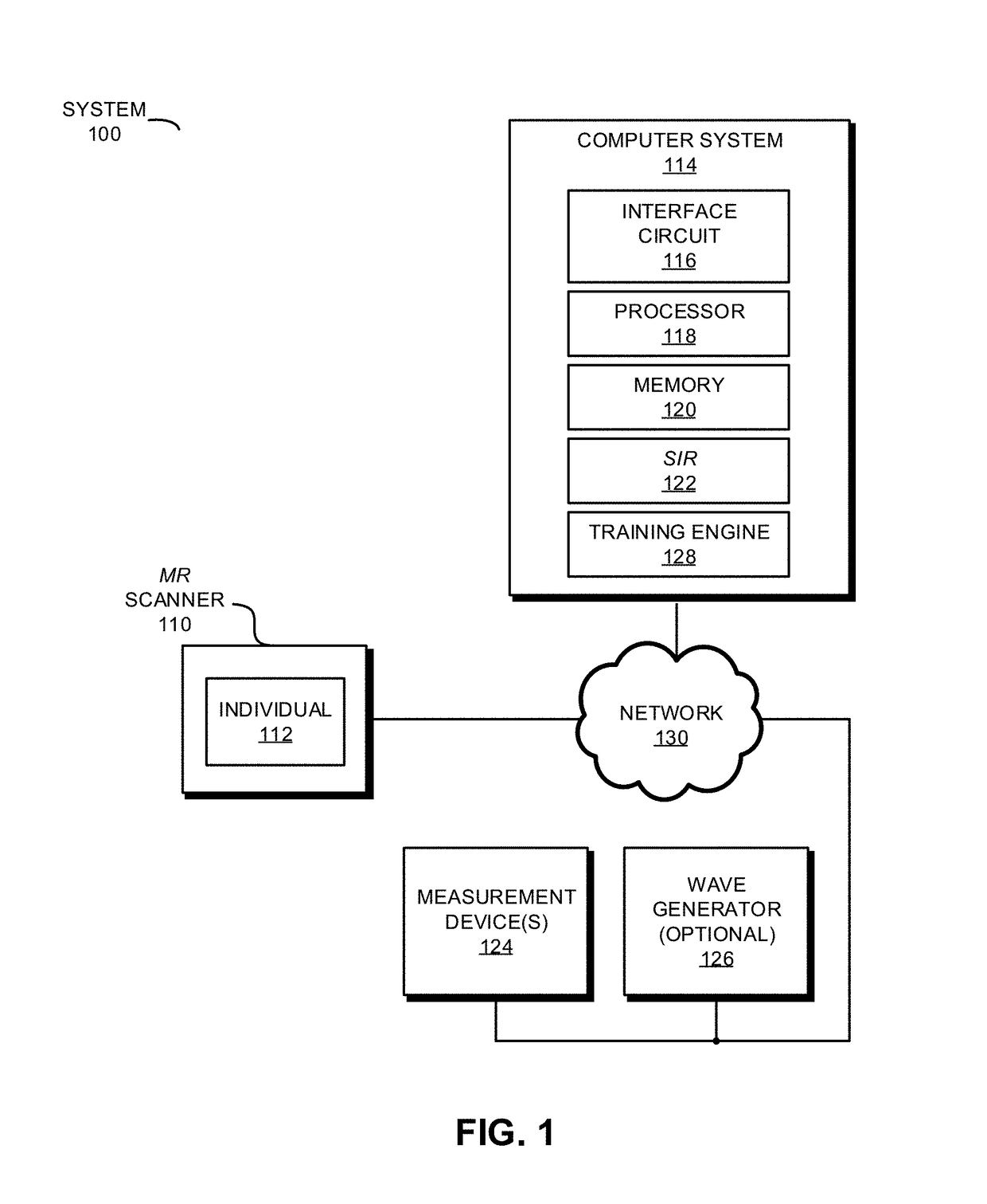
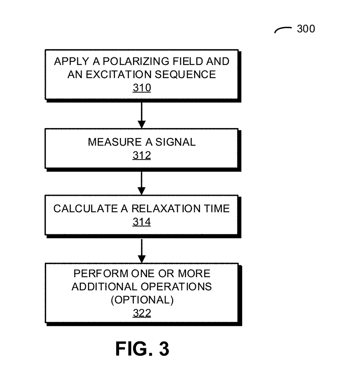
[0040]During operation, a system may apply a polarizing field and an excitation sequence to a sample. Then, the system may measure a signal associated with the sample for a time duration that is less than a magnitude of a relaxation time associated with the sample. Next, the system may calculate the relaxation time based on a difference between the measured signal and a predicted signal of the sample, where the predicted signal is based on a forward model, the polarizing field and the excitation sequence. After modifying at least one of the polarizing field and the excitation sequence, the aforementioned operations may be repeated until a magnitude of the difference is less than a convergence criterion. The one or more repetitions may occur without waiting for the sample to be completely relaxed or without resetting a state of the sample. Moreover, the calculations may be performed concurrently with the measurements and may not involve performing a Fourier transform on the measured ...


PUM


Abstract

During operation, a system may apply a polarizing field and an excitation sequence to a sample. Then, the system may measure a signal associated with the sample for a time duration that is less than a magnitude of a relaxation time associated with the sample. Next, the system may calculate the relaxation time based on a difference between the measured signal and a predicted signal of the sample, where the predicted signal is based on a forward model, the polarizing field and the excitation sequence. After modifying at least one of the polarizing field and the excitation sequence, the aforementioned operations may be repeated until a magnitude of the difference is less than a convergence criterion. Note that the calculations may be performed concurrently with the measurements and may not involve performing a Fourier transform on the measured signal.

Description

CROSS-REFERENCE TO RELATED APPLICATION[0001]This application claims priority under 35 U.S.C. §120 to: U.S. Non-Provisional application Ser. No. 15 / 089,571, entitled “Field-Invariant Quantitative Magnetic-Resonance Signatures,” by Jeffrey H. Kaditz and Andrew G. Stevens, filed on Apr. 3, 2016; and U.S. Non-Provisional application Ser. No. 15 / 169,719, entitled “Fast Scanning Based on Magnetic-Resonance History,” by Jeffrey H. Kaditz and Andrew G. Stevens, filed on 31 May 2016, the contents of each of which are hereby incorporated by reference.[0002]This application also claims priority under 35 U.S.C. §119(e) to: U.S. Provisional Application Ser. No. 62 / 189,675, entitled “Systems and Method for Indexed Medical Imaging of a Subject Over Time,” by Jeffrey H. Kaditz and Andrew G. Stevens, Attorney Docket Number TSLH-P01.00, filed on Jul. 7, 2015; U.S. Provisional Application Ser. No. 62 / 213,625, entitled “Systems and Method for Indexed Medical Imaging of a Subject Over Time,” by Jeffrey ...

Claims


Application Information

Patent Timeline
Patent Type & Authority Applications(United States)
IPC IPC(8): G01R33/44
CPCG01R33/445G01R33/448G01N24/08G01R33/465G01R33/48G01R33/4804G01R33/56358G01R33/50G01R33/546
Inventor KADITZ, JEFFREY HOWARDPOLYMERIDIS, ATHANASIOSVILLENA, JORGE FERNANDEZRAMASWAMY, DEEPAKWHITE, JACOB
Owner Q BIO INC
Why Eureka
Try Eureka