
DC-balanced and non-DC-balanced drive schemes for liquid crystal devices

Inactive Publication Date: 2003-01-14
CITIZEN FINETECH MIYOTA CO LTD
View PDF20 Cites 163 Cited by
  • Summary
  • Abstract
  • Description
  • Claims
  • Application Information

AI Technical Summary

Benefits of technology

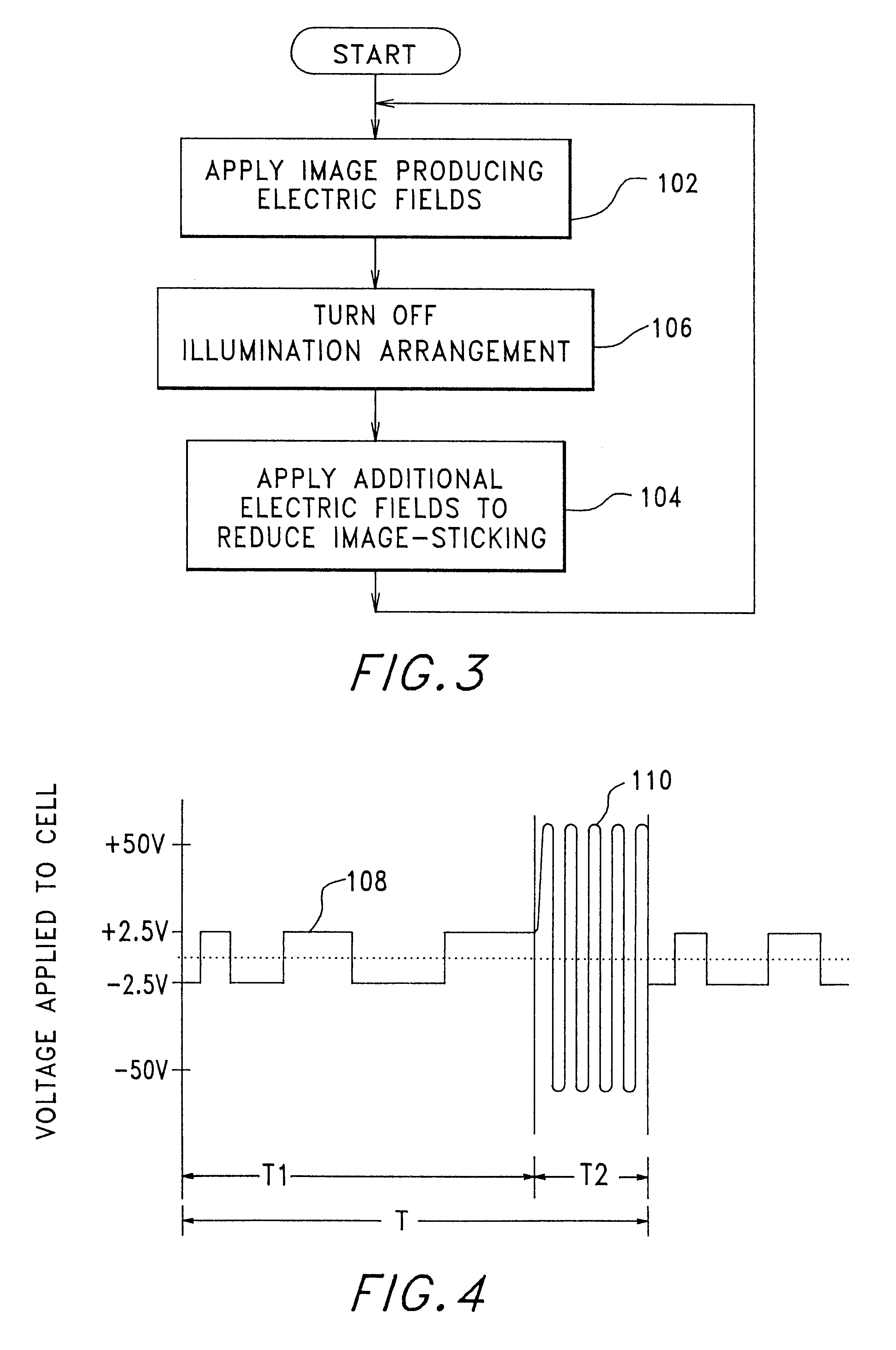
The setting of the pixel electrodes during the second portion of the given period of time may include inverting the polarity of the fields applied to the pixels and increasing the magnitude of the electric fields. The setting of the pixel electrodes during the second portion of the given period of time may include shortening the time duration of the electric fields by an amount proportional to the increase in the magnitude of the electric fields. The second portion of the given period of time may be less than or equal to about forty-five percent of the duration of the given period of time.
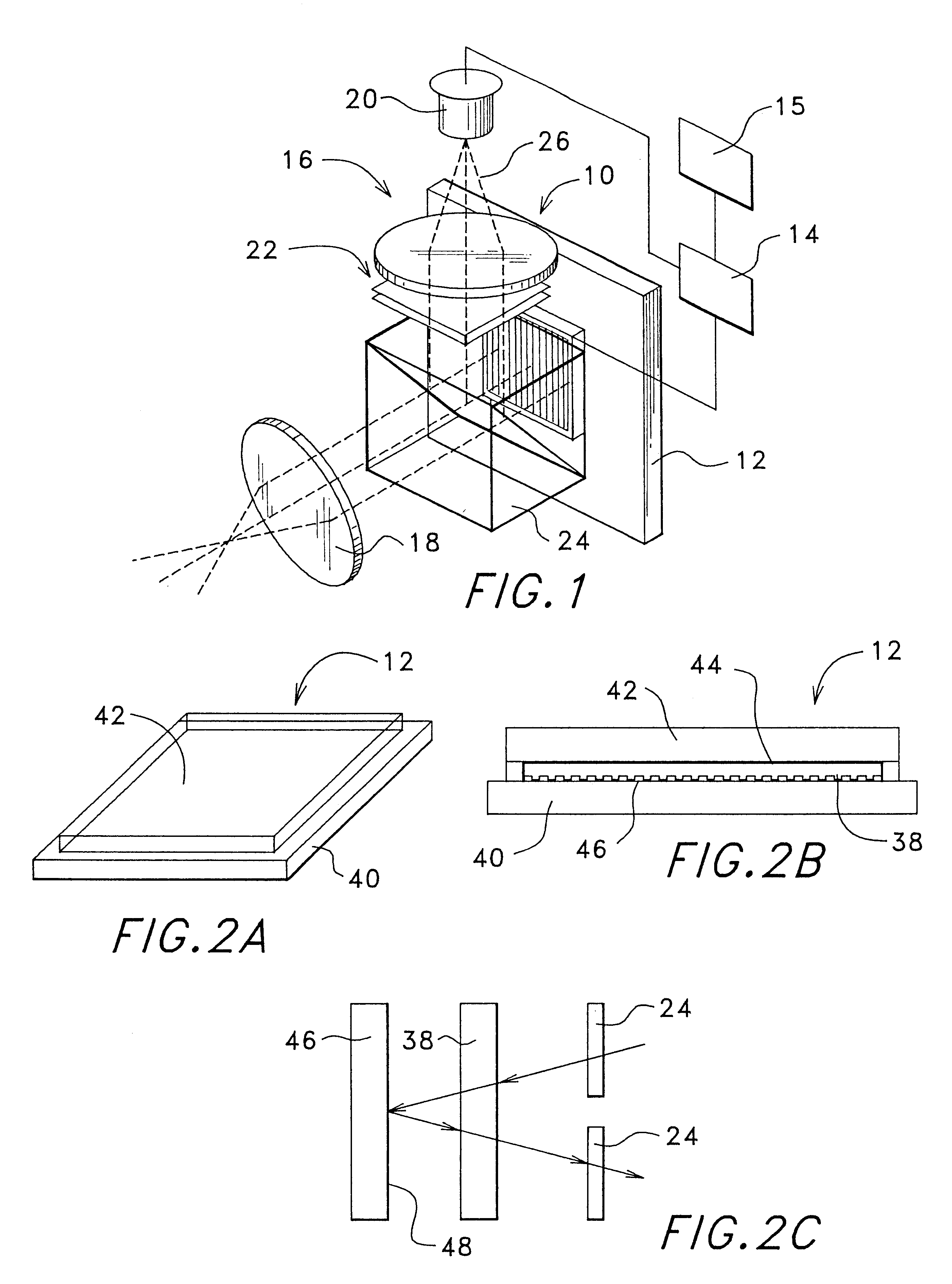
The present invention also relates to a method for operating a liquid crystal display during a given period of time, the method using input image data to control how the display is operated, the display creating visible images at a viewing area. The method includes applying a first series of voltage signals to the liquid crystal display during one portion of the period of time, the first series of voltage signals being arranged to produce an image as represented by the input image data. The method also includes allowing the display to be viewed at the viewing area, while the image is being produced by the first series of voltage signals applied to the display, by allowing illumination light to be directed to the display and from the display to the viewing area. The method also includes applying a second series of voltage signals to the liquid crystal display during another portion of the period of time, the second series of voltage signals being arranged to produce an inverse image, the second series of voltage signals being related to the first series as being inverted in polarity relative to the first series, having an increased magnitude relative to the first series, and having a shorter time duration than the first series. The method also includes substantially preventing the display from being viewed at the viewing area, while the inverse image is being produced by the second series of voltage signals applied to the display, by substantially preventing illumination light from reaching the viewing area.

Problems solved by technology

Because currently available liquid crystal materials manufactured using currently available manufacturing processes are not completely insulating, and because currently available assembly processes for manufacturing liquid crystal SLMs may introduce contaminants into the SLM assembly, this formation of electric fields across the liquid crystal material may cause leakage current to flow through the liquid crystal material while the electric fields are applied to the material.
If these electric fields are not balanced, the unbalanced fields (or the unbalanced leakage current) are believed to cause the degradation of the electro-optic characteristics of the liquid crystal material, thereby dramatically reducing the effectiveness and useful life of the material as a light modulating medium.
The presence of unbalanced fields across the light modulating medium tends to polarize or bias the light modulating medium if the electric fields are not balanced over time.
This sticking or build up of ionic charges tends to interfere with the electric fields subsequently applied to the light modulating medium and therefore interfere with the operation of the spatial light modulator.
This interference typically results in image sticking that interferes with the proper operation of the display system.
In the case of an active matrix image generating system or display, the image produced by the SLM during the time in which the frame is inverted for purposes of DC-balancing is not typically made available to the user.
Neither of these situations would provide a usable display.
However, this approach substantially limits the brightness and efficiency of the system.
Although these compensator cell arrangements appear to work well, they increase the complexity and cost of the display system by requiring the use of a compensator cell and in many cases other additional components.
These methods and apparatus will not make a successful display if they are applied to a FLC material that is not bistable.
A passive matrix display and the associated methods of operation cannot accomplish such continuous application of the electric field.

Method used


Image

  • DC-balanced and non-DC-balanced drive schemes for liquid crystal devices
  • DC-balanced and non-DC-balanced drive schemes for liquid crystal devices
  • DC-balanced and non-DC-balanced drive schemes for liquid crystal devices

Examples


Embodiment Construction

An invention is described herein for providing a method of operating a liquid crystal cell during a given period of time without requiring DC-balancing of the cell. In the following description, numerous specific details are set forth in order to provide a thorough understanding of the present invention. However, it will be obvious to one skilled in the art that the present invention may be embodied in a wide variety of specific configurations. Also, well known liquid crystal cell manufacturing processes and known methods of controlling liquid crystal cells using various electrical circuits will not be described in detail herein so as not to unnecessarily obscure the present invention.

The method of the present invention may be used with a wide variety of types of liquid crystal cells that may be used in a wide variety of specific applications. However, for purposes of an example, the method of the present invention will be described with reference to a ferroelectric liquid crystal d...


PUM


Abstract

A method of operating a liquid crystal cell includes DC-balancing by displaying an inverse image with electric fields of increased magnitude relative to the image producing electric fields. While the inverse image is displayed the image is prevented from being visible by either turning off the light source or re-directing or blocking the light from reaching the viewing area. The image producing electric fields and the inverse image producing electric fields are such that the cumulative time integral of the electric fields that are present in one direction across the liquid crystal material is substantially equal to the cumulative time integral of the electric fields that are present in the opposite direction during the given period of time during the operation of liquid crystal cell. The time duration of the inverse image portion is shorter than the time duration of the image portion by an amount proportional to the increased magnitude of the additional electric fields. Because of the shorter time period when no image is visible, the system brightness is increased.

Description

FIELD OF THE INVENTIONThe present invention relates generally to liquid crystal devices and more specifically to schemes for driving a liquid crystal cell, such as a ferroelectric liquid crystal cell, both with and without requiring DC-balancing of the liquid crystal cell.BACKGROUND OF THE INVENTIONIn the field of image generators and especially those using spatial light modulators (SLMs), it is well known that stationary and moving images, either monochrome or color, may be sampled and both color-separated and gray-scale separated pixel by pixel. These pixelated separations may be digitized, forming digitized images that correspond to the given images. These digitized images are used by devices in this field to create visual images that can be used for a direct visual display, a projected display, a printer device, or for driving other devices that use visual images as their input.One such novel image generator is disclosed in U.S. Pat. No. 5,748,164, entitled ACTIVE MATRIX LIQUID ...

Claims


Application Information

Patent Timeline
IPC IPC(8): G09G3/36
CPCG09G3/3651G09G3/36G09G3/3614G09G3/3655G09G2320/0257G09G2310/06G09G2310/063G09G2320/02G09G2320/0204G09G2310/0251
Inventor HANDSCHY, MARK A.XUE, JIUZHIJI, LIANHUA
Owner CITIZEN FINETECH MIYOTA CO LTD
Learn More