Cleaner head for a vacuum cleaner

a vacuum cleaner and cleaner head technology, applied in the field of vacuum cleaners, can solve the problems of cleaner heads that suffer from increased weight and bulk, drop in performance, and increase complexity

Inactive Publication Date: 2017-10-12
DYSON TECH LTD
View PDF5 Cites 6 Cited by
  • Summary
  • Abstract
  • Description
  • Claims
  • Application Information

AI Technical Summary

Benefits of technology

[0006]It is one object of the present invention to mitigate or obviate at least one of the above disadvantages, and / or to provide an improved or alternative cleaner head or vacuum cleaner.

Problems solved by technology

While tailoring the brush bar of a cleaner head to a particular surface may improve the pickup performance of the cleaner head when cleaning that particular surface, it can also result in a drop in performance when the cleaner head is used on a different surface.
Existing attempts to address this problem generally result in cleaner heads that suffer from increased weight and bulk, increased complexity, reduced ease of use and / or reduced rotational power delivered to a particular brush bar.

Method used


Image

  • Cleaner head for a vacuum cleaner
  • Cleaner head for a vacuum cleaner
  • Cleaner head for a vacuum cleaner

Examples


Embodiment Construction

[0057]Throughout the description and drawings, corresponding reference numerals denote corresponding features.

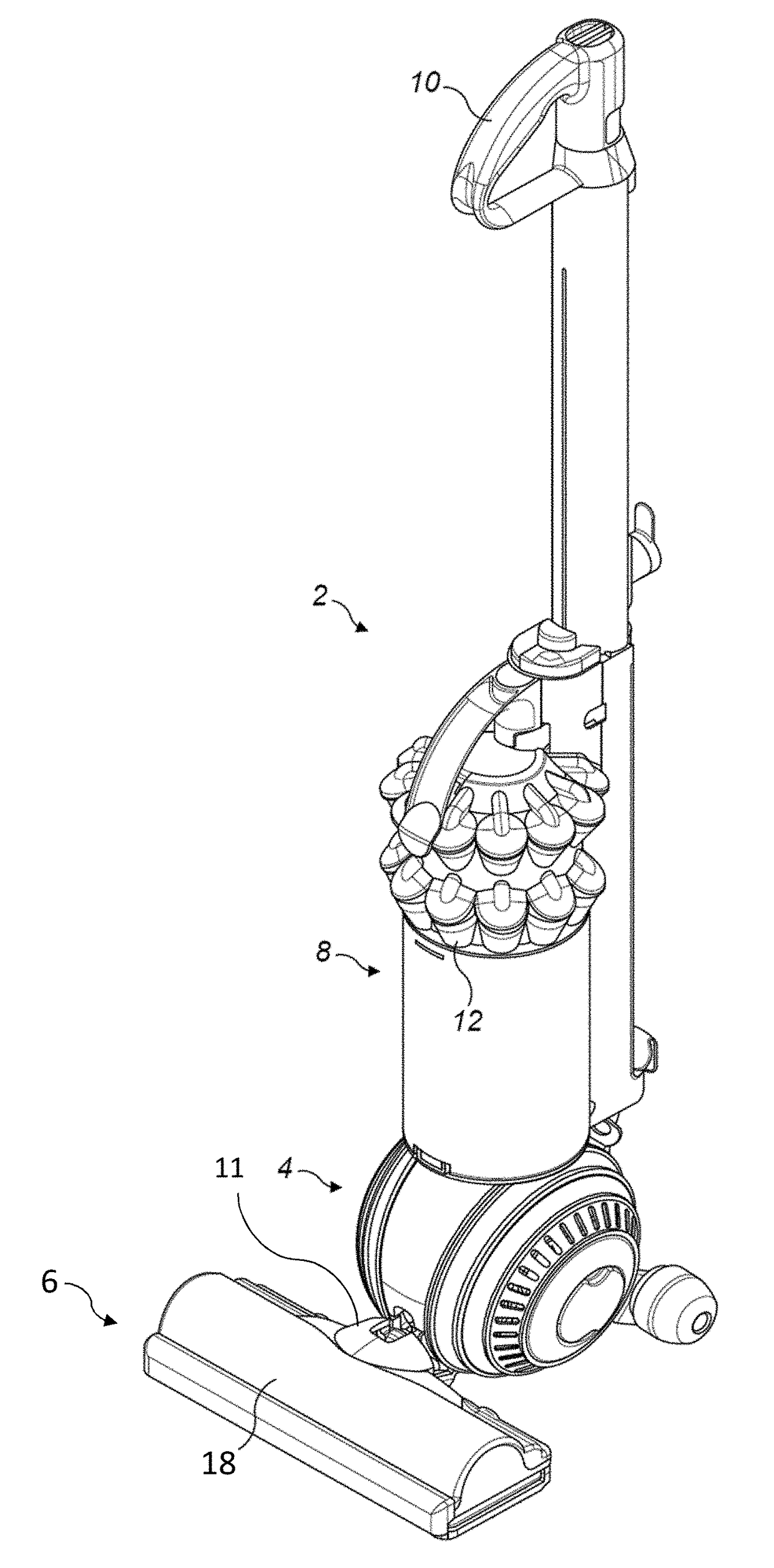
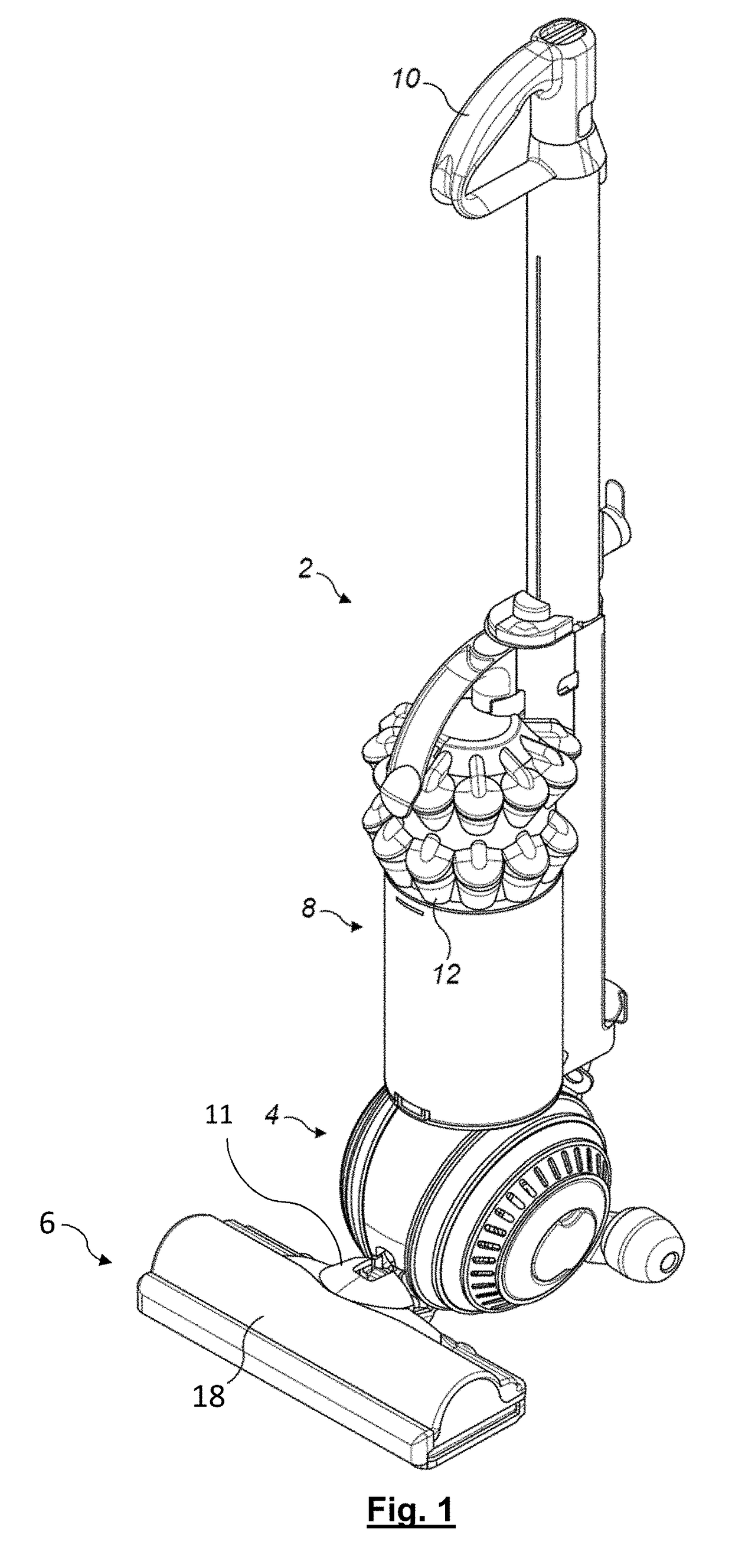
[0058]FIG. 1 shows a vacuum cleaner 2 which is useful for understanding the invention. This example is an upright vacuum cleaner 2. It has a rolling head assembly 4 which carries a fixed cleaner head 6, and an ‘upright’ body 8. The upright body can be reclined relative to the head assembly 4, and includes a handle 10 for maneuvering the vacuum cleaner 2 across the floor. In use, a user grasps the handle 10 and reclines the upright body 8 until the handle 10 is disposed at a convenient height for the user. The user can then roll the vacuum cleaner 2 across the floor using the handle 10 in order to pass the cleaner head 6 over the floor and pick up dust and other debris therefrom. The dust and debris is drawn into a suction chamber (not visible) of the cleaner head by a suction generator in the form of a motor-driven fan (not visible) housed on board the vacuum cleaner 2. The ...


PUM


Abstract

A cleaner head for a vacuum cleaner includes a body that defines a suction chamber, the suction chamber having a suction inlet for engaging a surface to be cleaned, and an outlet for fluid connection to a suction generator of a vacuum cleaner. The cleaner head further includes first and second brush bars each configured to contact a surface engaged by the suction inlet, and a drive mechanism which has an actuator. The drive mechanism is configured to rotate the brush bars about respective axes. The drive mechanism is also configured to rotate the first brush bar independently of the second brush bar, and to rotate the second brush bar independently of the first brush bar.

Description

REFERENCE TO RELATED APPLICATIONS[0001]This application claims the priority of United Kingdom Application No. 1606174.9, filed Apr. 8, 2016, the entire contents of which is incorporated herein by reference.FIELD OF THE INVENTION[0002]The present invention relates to the field of vacuum cleaners, and in particular to cleaner heads for vacuum cleaners.BACKGROUND OF THE INVENTION[0003]Cleaner heads may incorporate rotatable brush bars, such as those which are used to improve the cleaning performance of the cleaner head and thus of the vacuum cleaner as a whole. Such cleaner heads may be used with a vacuum cleaner that may be of any general type. For example, the cleaner head may be a fixed cleaner head on an upright vacuum cleaner, or alternatively it may be the cleaner head of a floor tool used with a cylinder vacuum cleaner or stick-vac cleaner.[0004]It is conventional to provide the cleaner head of a vacuum cleaner with a rotatable brush bar. The design of the brush bar can be tailo...

Claims


Application Information

Patent Timeline
Patent Type & Authority Applications(United States)
IPC IPC(8): A47L9/04A47L9/16A47L5/30
CPCA47L9/0488A47L5/30A47L9/1616A47L9/0444A47L9/0477A47L9/0411A47L9/0416A47L9/04
Inventor DOBSON, MATTHEW JOHN
Owner DYSON TECH LTD
Why Eureka
Try Eureka