Sprag clutch cassette driver

a cassette driver and clutch technology, applied in the direction of clutches, hubs, freewheel clutches, etc., can solve the problem of not completely achieving this goal in a cost-effective manner

Inactive Publication Date: 2017-10-12
NORTH FLORIDA UNIV OF
View PDF3 Cites 1 Cited by
  • Summary
  • Abstract
  • Description
  • Claims
  • Application Information

AI Technical Summary

Benefits of technology

[0008]The present invention may address one or more of the problems and deficiencies of the prior art discussed above. However, it is contemplated that the invention may prove useful in addressing other problems and deficiencies in a number of technical areas. Therefore, the claimed invention should not necessarily be construed as limited to addressing any of the particular problems or deficiencies discussed herein.

Problems solved by technology

However, it does not completely accomplish this goal in a cost-effective manner, as friction loss during freewheeling should be minimized to preserve the cyclist's energy and enhance performance of the bicycle.
Furthermore, where a definition or use of a term in a reference, which is incorporated by reference herein, is inconsistent or contrary to the definition of that term provided herein, the definition of that term provided herein applies and the definition of that term in the reference does not apply.

Method used


Image

  • Sprag clutch cassette driver
  • Sprag clutch cassette driver
  • Sprag clutch cassette driver

Examples


example 1

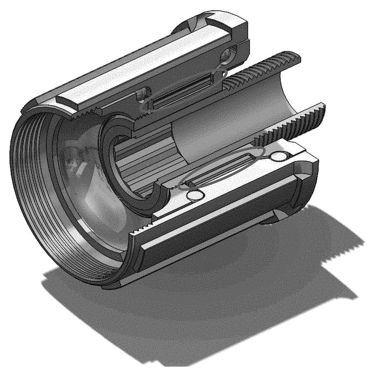
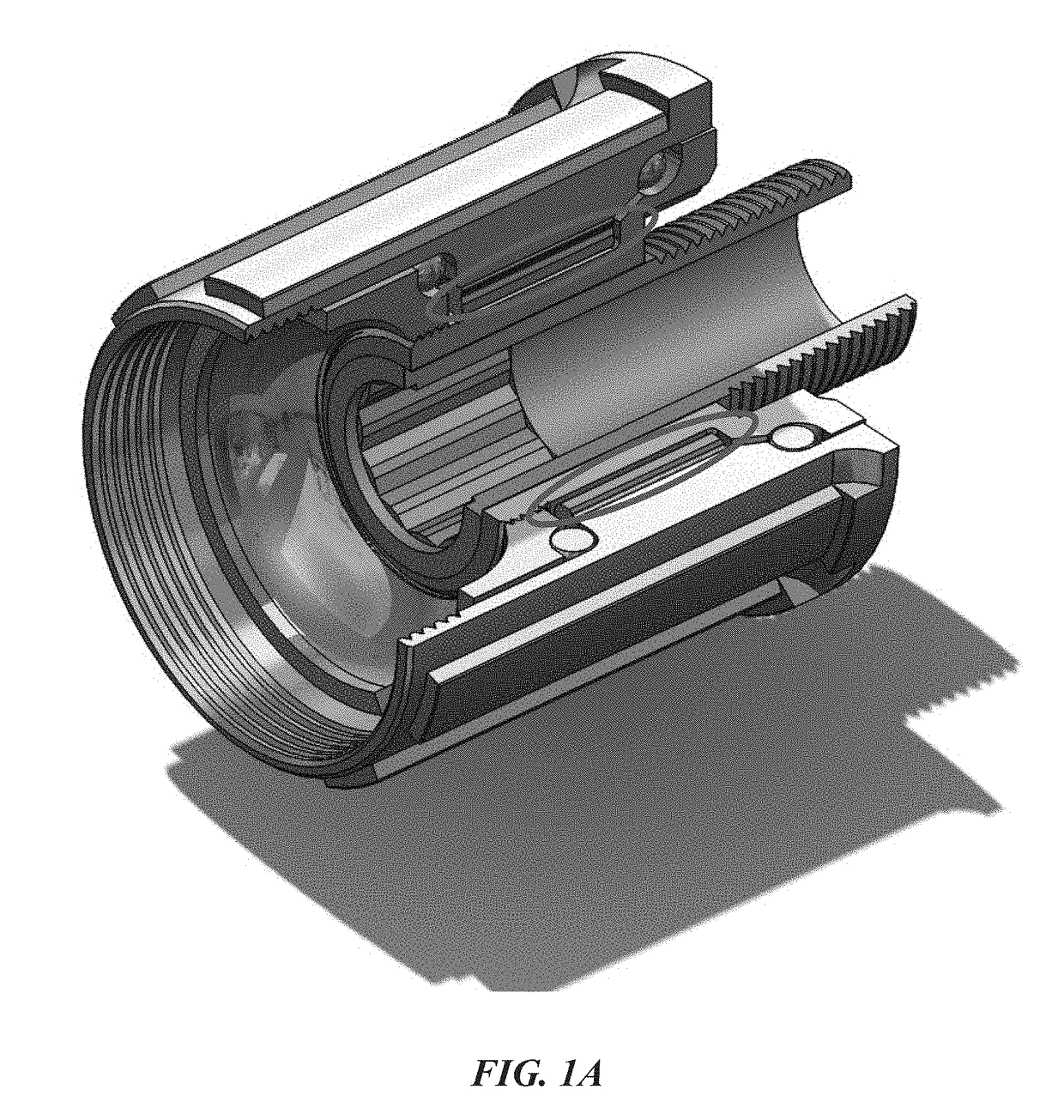
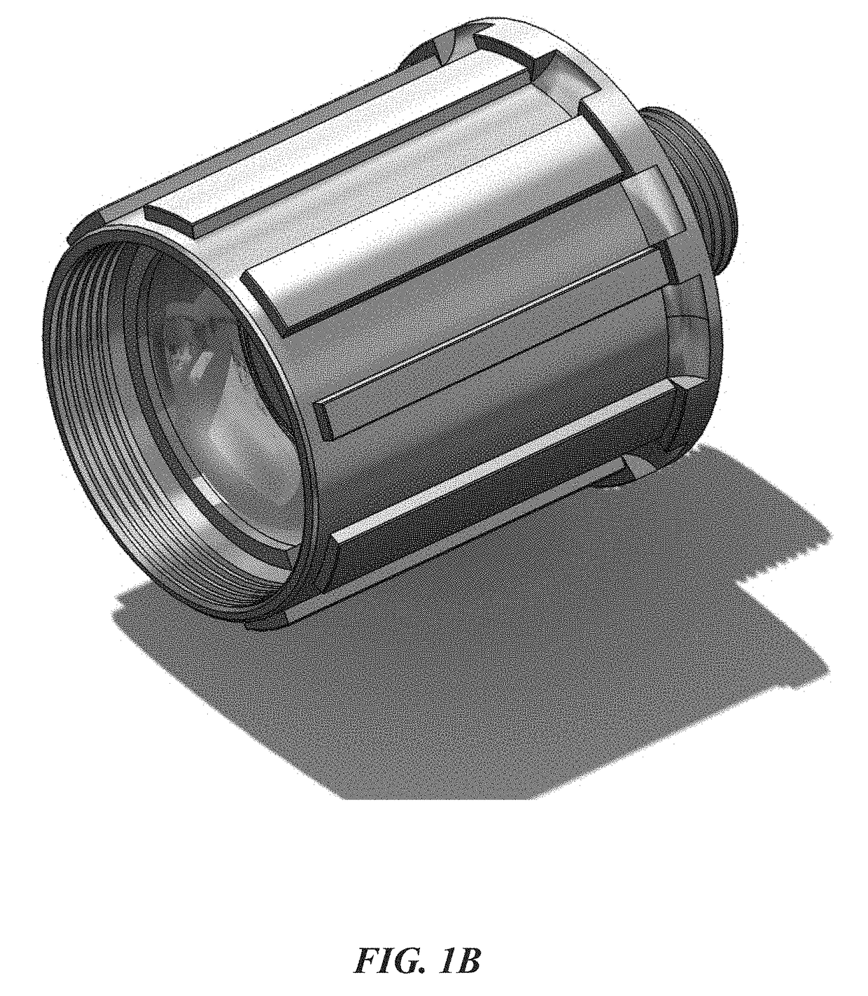
[0037]In an embodiment, as can be seen in FIG. 1A-1C and 2-4 the sprag clutch is positioned in the annular cavity within the cassette driver of the bicycle. The sprags contact the exterior surface of the inner race and the interior surface of the cassette driver shell. The sprags only come in contact with surfaces within the cassette driver.

[0038]It is well-known to remove the clutch mechanism from a bicycle's hub itself and place it into a cassette driver, considering many cassette drivers have a clutch mechanism. However, most, if not all, bicycles available use a ratchet and pawl mechanism in the cassette driver. However, using a sprag clutch mechanism within the cassette driver, as in the current invention, is novel and non-obvious as it provides the benefits of a sprag and clutch mechanism, while greatly reducing the cost to gain these benefits when compared to replacing an entire rear wheel hub. It can even be said that the current cassette driver essentially is the sprag clut...

example 2

[0039]It is an object of the current invention to provide instantaneous engagement, reliability, and a quieter ride, which can be provided by a sprag clutch fitted into a new or existing bicycle hub, specifically in the cassette driver. In designing this embodiment of the current invention, the sprag clutch must be able to withstand an infinite number of cycles without failing due to the fact that a hub failing could result in serious injury to the bicycle user if the wheel seizes from clutch failure. The clutch must also operate with the intended purpose of the sprags.

Methodology

[0040]The magnitude of torque applied by the rider is dependent upon their weight. However, the force on each sprag is ultimately determined by the radii of the races. The radii are constrained by the typical cassette driver body size, for a seamless integration of use. If not, either a different cassette driver body or integrating the clutch within the wheel hub shell is needed. The dimensions of a typical...


PUM


Abstract

A sprag one-way clutch (OWC) used within a cassette driver of the rear hub assembly of a bicycle. The new cassette driver delivers improved performance the reduction of rotation of the crank arm required before engagement within the cassette driver when the cyclist applies force to the pedals. Additionally, the sprag clutch smooth engagement minimizes friction loss during free-wheeling, therefore increasing drivetrain efficiency. These enhancements provide both safety and performance benefits by giving the cyclist greater control in moving between pedaling and free-wheeling. The current cassette driver design utilizes a sprag OWC for engagement without any modifications to current bicycle designs. A sprag cage may be used to provide a framework to support and properly position the sprags.

Description

CROSS-REFERENCE TO RELATED APPLICATIONS[0001]This nonprovisional application is claims priority to U.S. Provisional Patent Application No. 62 / 318,799, entitled “Sprag Clutch Cassette Driver”, filed Apr. 6th, 2016 by the same inventors, the entirety of which is incorporated herein by reference.BACKGROUND OF THE INVENTION1. Field of the Invention[0002]This invention relates, generally, to bicycle drivetrains. More specifically, it relates to sprag clutch cassette drivers.2. Brief Description of the Prior Art[0003]The majority of recreational mountain bicycles utilize a ratchet and pawl clutch system in the rear wheel hub which allows for the transfer of torque to the rear wheel when pedaling in one direction and free rotation if pedaling in the opposite direction. As seen in FIG. 5, the pawl can have a significant gap in between teeth on the ratchet before the pawl engages the outer race of the system and torque is transferred to the wheel. On the other hand, a sprag system engages mu...

Claims


Application Information

Patent Timeline
Patent Type & Authority Applications(United States)
IPC IPC(8): B60B27/00F16D41/24B60B27/02
CPCB60B27/00B60B27/02B60B2900/212B60B2900/1212F16D41/24F16D2041/0603F16D41/067F16D41/28B60B27/023B60B27/047B60B27/0026F16D41/07
Inventor MILLER, RYANPOLITO, MARCUSRILLSTONE, RYAN
Owner NORTH FLORIDA UNIV OF
Why Eureka
Try Eureka