Optical microcavity for a high-contrast display

a high-contrast display and microcavity technology, applied in the field of optical display technology, can solve the problems of high power requirements, significant limitations of color filters, and substantial losses in optical intensity, and achieve the effect of improving the color gamut and output efficiency of advanced displays

Active Publication Date: 2017-10-12
THE BOARD OF TRUSTEES OF THE UNIV OF ILLINOIS
View PDF2 Cites 14 Cited by
  • Summary
  • Abstract
  • Description
  • Claims
  • Application Information

AI Technical Summary

Benefits of technology

[0008]An optical microcavity for a high-contrast display comprises an enclosed cavity having a front wall and a back wall, where the front wall comprises a pinhole opening for emission of light from the cavity and the back wall is configured to generate or transmit light into the cavity. An outer surface of the front wall absorbs some or substantially all optical wavelengths of externally incident light so as to appear black or colored. An inner surface of the front wall and any sidewalls that may be present comprises a light reflectivity of greater than 90% to promote photon recycling within the cavity and light emission through the pinhole opening.

Problems solved by technology

Since the color filter eliminates two out of three colors of the RGB (red-green-blue) spectrum, there may be substantial losses in optical intensity, which leads to higher power requirements.
Thus, color filters can impose significant limitations on the accessible color gamut and output efficiency of advanced displays.
LCD devices may suffer from a low ambient contrast ratio because of reflection of external light from the front surface.
One problem with this approach is that the light produced by the LCD also passes through the circular polarizer, which leads to significant absorption of the light.
However, OLED devices may suffer from a low ambient contrast ratio because of reflection of external light from the front surface.
One problem with this approach is that the light produced in the emissive layer of the OLED also passes through the circular polarizer, which can lead to absorption of more than 50% of the photons generated by the OLED.

Method used


Image

  • Optical microcavity for a high-contrast display
  • Optical microcavity for a high-contrast display
  • Optical microcavity for a high-contrast display

Examples


Embodiment Construction

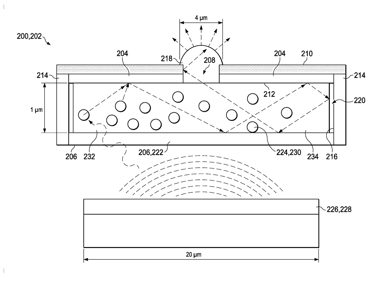
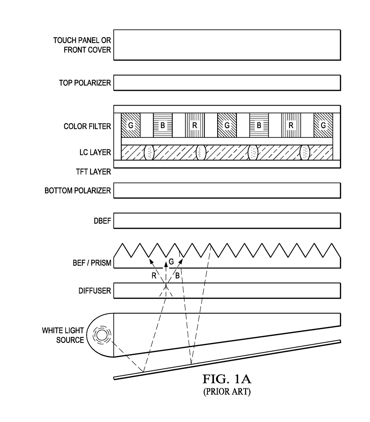
[0015]The present disclosure provides a new design architecture for advanced displays that utilizes an optical microcavity to produce color output. The new design may reduce or eliminate the need for color filters and polarization filters, the former of which tends to be a major detriment to obtaining high optical efficiencies in conventional backlit LCDs, and the latter of which is often required to enhance ambient contrast in both LCDs and OLEDs. Incorporation of the optical microcavity into backlit LCD and OLED devices may lead to a reduction in the required power as well as improved display performance.

[0016]Referring now to FIG. 2, an optical microcavity 200 for a high-contrast display includes an enclosed cavity 202 comprising a front wall 204 and a back wall 206, where the front wall 204 includes a pinhole opening 208 for emission of light from the cavity 202, and the back wall 206 is configured to generate or transmit light into the cavity 202. The back wall 206 may also be ...


PUM

PropertyMeasurementUnit
light reflectivityaaaaaaaaaa
reflectivityaaaaaaaaaa
photon extraction efficiencyaaaaaaaaaa

Abstract

An optical microcavity for a high-contrast display comprises an enclosed cavity having a front wall and a back wall, where the front wall comprises a pinhole opening for emission of light from the cavity and the back wall is configured to generate or transmit light into the cavity. An outer surface of the front wall absorbs some or substantially all optical wavelengths of externally incident light so as to appear black or colored. An inner surface of the front wall comprises a light reflectivity of greater than 90% to promote photon recycling within the cavity and light emission through the pinhole opening.

Description

RELATED APPLICATION[0001]The present patent document claims the benefit of priority under 35 U.S.C. §119(e) to U.S. Provisional Patent Application Ser. No. 62 / 321,263, filed on Apr. 12, 2016, which is hereby incorporated by reference in its entirety.TECHNICAL FIELD[0002]The present disclosure relates generally to optical display technology, and more specifically to a microcavity device to improve display contrast.BACKGROUND[0003]LED-backlit liquid crystal display (LCD) devices currently dominate the color display market, in part because they are relatively inexpensive and reliable to produce. The schematic of FIG. 1A illustrates a conventional LED-backlit LCD, which produces color by filtering white light through color filters placed adjacent to the liquid crystal (LC) layer. Each sub-pixel of the display contains a color filter to output either red, green or blue light. Since the color filter eliminates two out of three colors of the RGB (red-green-blue) spectrum, there may be subs...

Claims


Application Information

Patent Timeline
Patent Type & Authority Applications(United States)
IPC IPC(8): G02F1/1335H01L51/52G02F1/1333
CPCG02F1/1336G02F1/133528G02F1/133509G02F1/13338H01L51/5281G02F2001/133614G02B6/0046G02B6/0053G02B6/0051G02B6/0055G02F2203/34G02F1/133504G02F1/133606G02F1/133614H10K50/856H10K50/86
Inventor BRAUN, PAUL V.CIFCI, OSMAN S.EPSTEIN, ERIC S.CHEN, HAOXU, LUNUZZO, RALPH G.
Owner THE BOARD OF TRUSTEES OF THE UNIV OF ILLINOIS
Why Eureka
Try Eureka