Systems and devices for motion tracking, assessment, and monitoring and methods of use thereof

a technology of motion tracking and monitoring devices, applied in the field of industrial athletes, can solve the problems of debilitating pain suffered by those experiencing a workplace injury, and achieve the effect of reducing the risk of injury

Active Publication Date: 2017-10-19
STRONG ARM TECH +1
View PDF8 Cites 19 Cited by
  • Summary
  • Abstract
  • Description
  • Claims
  • Application Information

AI Technical Summary

Benefits of technology

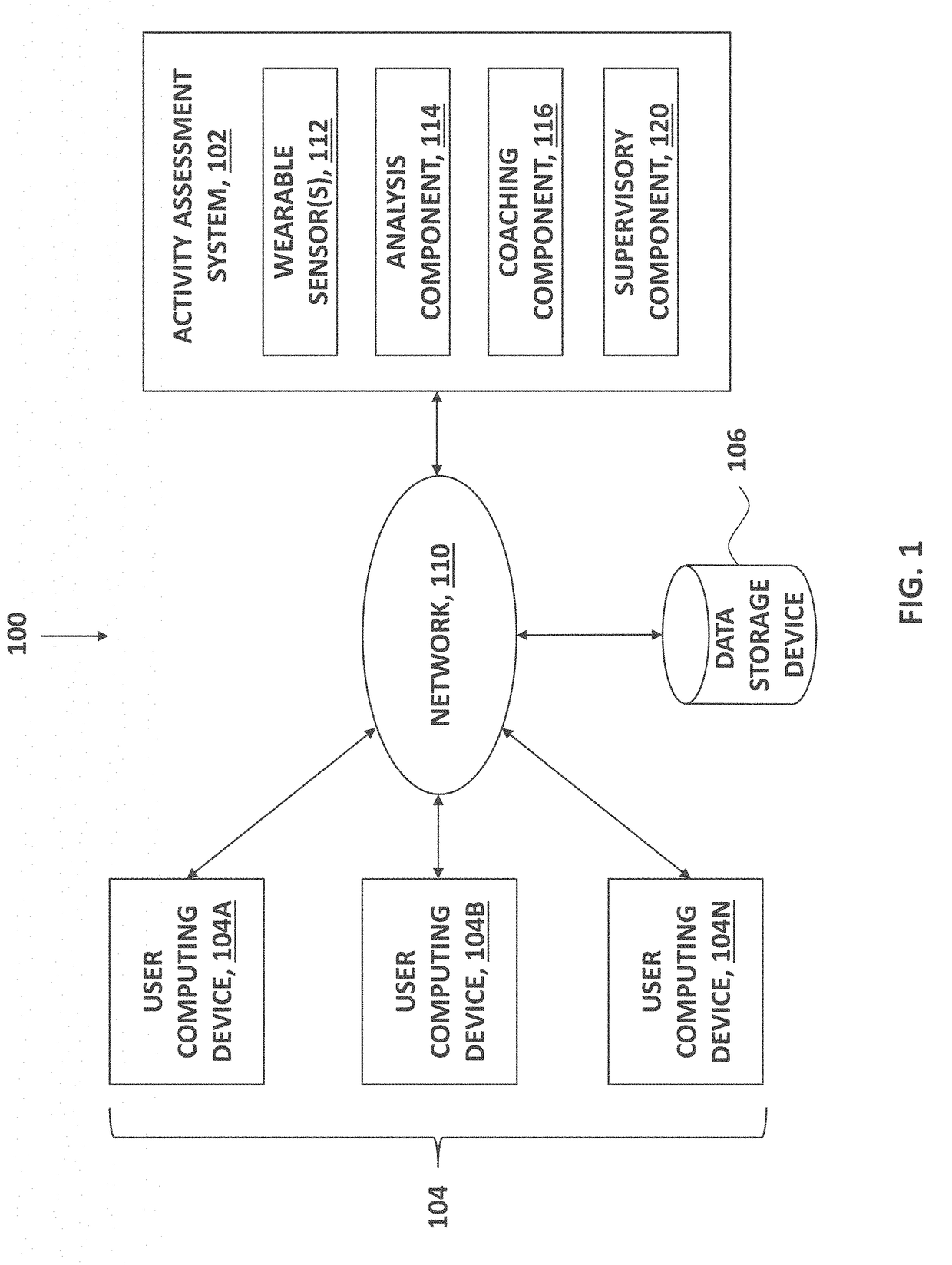
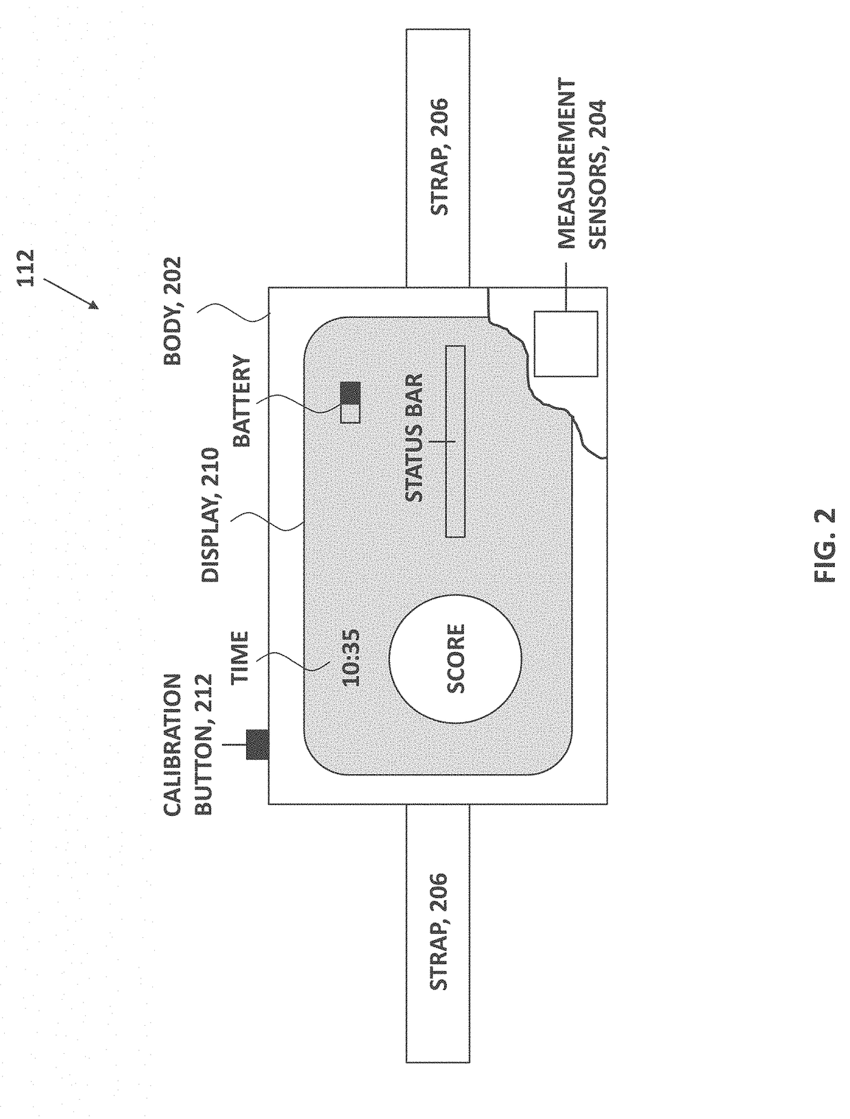
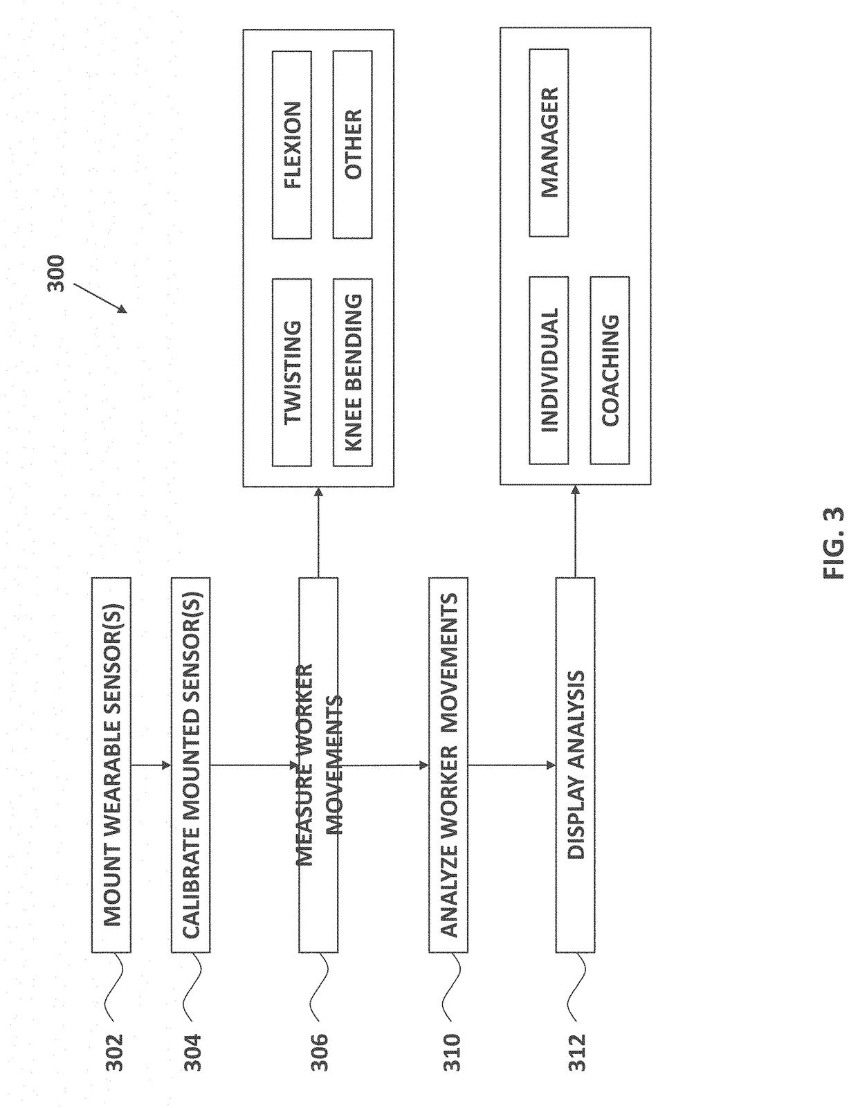
[0040]In some embodiments, a system includes a wearable sensor configured to be worn by a person and to record sensor data during an activity performed by the person, the sensor data comprising accelerometer data, gyroscope data, and magnetometer data; an analysis element configured to: receive the sensor data from the wearable sensor, determine sensor orientation data of the wearable sensor during the activity based on the sensor data, the sensor orientation data including (a) yaw data of the wearable sensor, (b) pitch data of the wearable sensor, and (c) roll data of the wearable sensor, translate the sensor orientation data of the wearable sensor to person orientation data of the person during the activity, the person orientation data including (a) yaw data of the person, (b) pitch data of the person, and (c) roll data of the person, the translating including using at least one Tait-Bryan rotation, determine, for the person during the activity, (a) a lift rate, (b) a maximum sagittal flexion, (c) an average twist velocity, (d) a maximum moment, and (e) a maximum lateral velocity based on at least (a) the yaw data of the person, (b) the pitch data of the person, and (c) the roll data of the person, and determine a score representative of an injury risk to the person during the activity based on (a) the lift rate, (b) the maximum sagittal flexion, (c) the average twist velo

Problems solved by technology

More importantly, beyond the mere financial cost of such injuries, is t

Method used


Image

  • Systems and devices for motion tracking, assessment, and monitoring and methods of use thereof
  • Systems and devices for motion tracking, assessment, and monitoring and methods of use thereof
  • Systems and devices for motion tracking, assessment, and monitoring and methods of use thereof

Examples


Embodiment Construction

[0047]Among those benefits and improvements that have been disclosed, other objects and advantages of this invention will become apparent from the following description taken in conjunction with the accompanying figures. Detailed embodiments of the present invention are disclosed herein; however, it is to be understood that the disclosed embodiments are merely illustrative of the invention that may be embodied in various forms. In addition, each of the examples given in connection with the various embodiments of the invention which are intended to be illustrative, and not restrictive.

[0048]Throughout the specification and claims, the following terms take the meanings explicitly associated herein, unless the context clearly dictates otherwise. The phrases “in one embodiment,”“in an embodiment,” and “in some embodiments” as used herein do not necessarily refer to the same embodiment(s), though it may. Furthermore, the phrases “in another embodiment” and “in some other embodiments” as ...


PUM


Abstract

A system includes a wearable sensor configured to be worn by a person and to record sensor data during an activity performed by the person; an analysis element configured to receive the sensor data from the wearable sensor, determine sensor orientation data of the wearable sensor during the activity based on the sensor data, translate the sensor orientation data of the wearable sensor to person orientation data of the person during the activity, determine, for the person during the activity, (a) a lift rate, (b) a maximum sagittal flexion, (c) an average twist velocity, (d) a maximum moment, and (e) a maximum lateral velocity, and determine a score representative of an injury risk to the person during the activity based on such data; and a tangible feedback element configured to provide at least one tangible feedback based on the score so as to reduce the injury risk.

Description

CROSS-REFERENCE TO RELATED APPLICATION[0001]This application is a Section 111(a) application relating to and claiming the benefit of commonly owned, co-pending U.S. Provisional Patent Application No. 62 / 321,865, titled “MOTION TRACKING, ASSESSMENT, AND MONITORING,” having a filing date of Apr. 13, 2016, the contents of which are incorporated by reference herein in their entirety.FIELD OF THE INVENTION[0002]The field of invention relates to monitoring of industrial athletes to ensure that they are working safely.BACKGROUND OF THE INVENTION[0003]Workplace injuries in the United States alone cost approximately $250 billion per year, a figure which is expected to rise over time. One prominent example is back injuries. Each back injury is estimated to cost almost $60,000 on average, totaling an estimated $120 billion a year. More importantly, beyond the mere financial cost of such injuries, is the debilitating pain suffered by those experiencing a workplace injury. Accordingly, there exi...

Claims


Application Information

Patent Timeline
IPC IPC(8): A61B5/00A61B5/11
CPCA61B5/7275A61B5/6831A61B5/1118A61B5/7278A61B5/7455A61B2562/0219A61B5/742A61B5/486A61B5/1121A61B5/0022A61B5/7405A61B5/743G16H50/30G16H40/67G16H20/30A61B5/1116
Inventor PETTERSON, SEAN MICHAELKIM, MICHAEL DOHYUNARGONDIZZA, ALAN VITOSPINELLI, MICHAEL PATRICK
Owner STRONG ARM TECH
Why Eureka
Try Eureka