Failure detection device

a failure detection and detection device technology, applied in the direction of instruments, testing/monitoring control systems, combustion-air/fuel-air treatment, etc., can solve the problem of reducing the detection accuracy of sensor failure, and reduce the influence of environmental change, so as to improve the detection accuracy. the effect of sensor failur

Active Publication Date: 2017-10-19
IHI CORP
View PDF1 Cites 4 Cited by
  • Summary
  • Abstract
  • Description
  • Claims
  • Application Information

AI Technical Summary

Benefits of technology

[0015]In accordance with the present disclosure, such an influence of the environmental c

Problems solved by technology

As mentioned above, in the conventional failure detection method, each sensor value is affected by such an environmental change, whereby a small degree

Method used


Image

  • Failure detection device
  • Failure detection device
  • Failure detection device

Examples


first embodiment

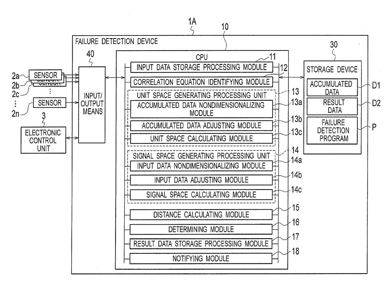
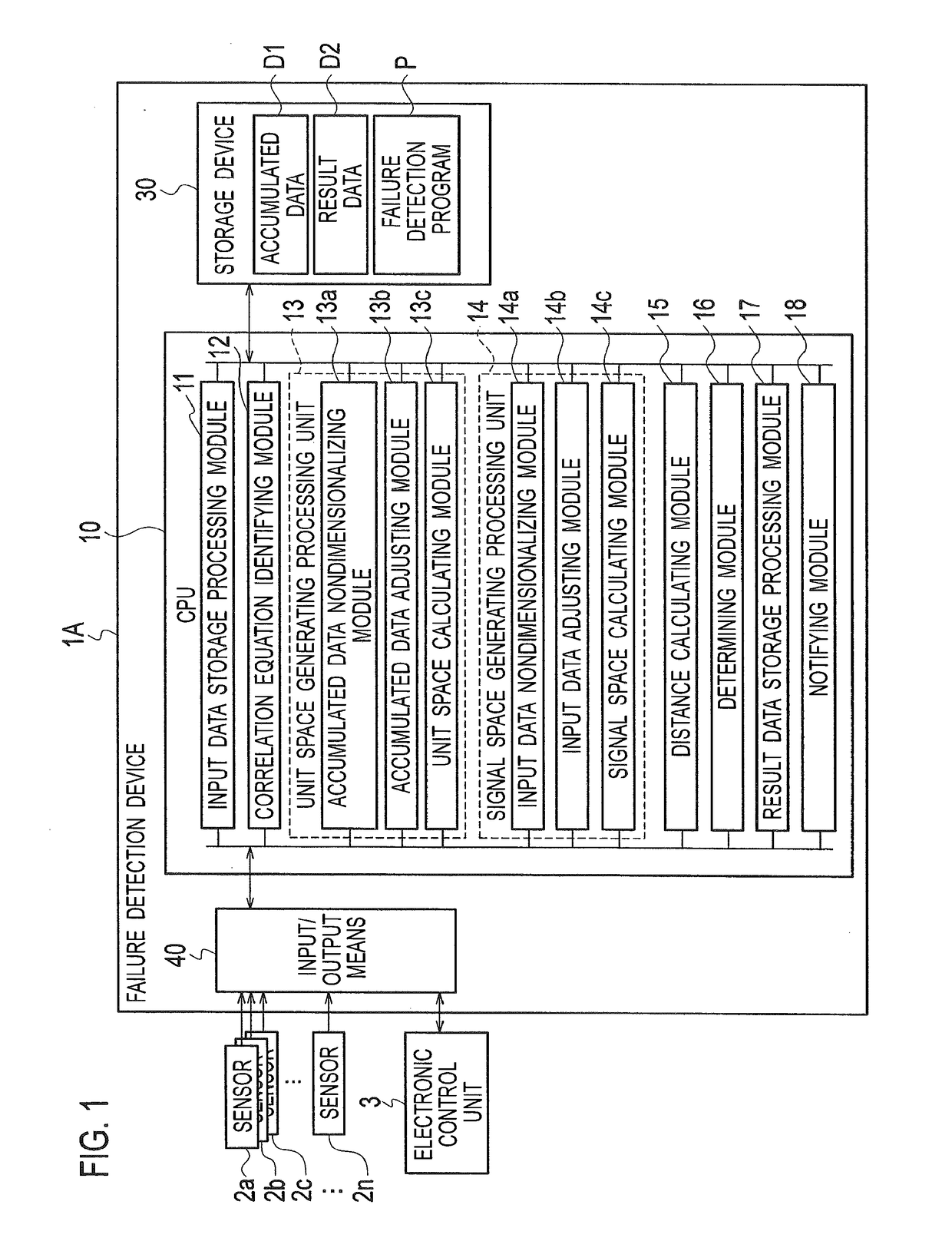
[0026]As shown in FIG. 1, in the gas turbine engine of the aircraft, a failure detection device 1A according to a first embodiment is connected to a plurality of sensors 2a to 2n which measure the respective values, and to an electronic control unit 3 for use in controlling the gas turbine engine of the aircraft and controlling other devices of the aircraft, and detects whether or not there are failures of the respective sensors 2a to 2n by the error variance method of the MT system by using data inputted from the respective sensors 2a to 2n and the electronic control unit 3, and in addition, detects which of the sensors 2a to 2n may have caused a failure in a case where there is a failure.

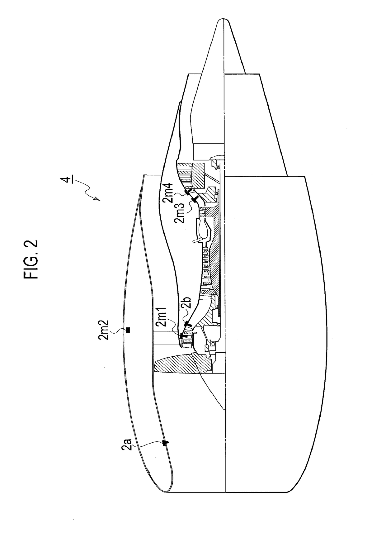
[0027]The number of sensors connected to the failure detection device 1a is not limited. For example, as the sensors 2a to 2n, there are conceivable: a sensor that measures an inlet temperature of the gas turbine engine; a sensor that measures an inlet temperature of a compressor owned by the gas ...

second embodiment

[0084]As shown in FIG. 8, a failure detection device 1B according to a second embodiment is also connected to the plurality of sensors 2a to 2n and the electronic control unit 3. This failure detection device 1B detects whether or not there are failures of the respective sensors 2a to 2n by using not the MT system but the neural network, and in addition, detects which of the sensors 2a to 2n may have caused a failure in a case where there is a failure.

[0085]In comparison with the failure detection device 1A mentioned above by using FIG. 1, the failure detection device 1B is different therefrom in not including the unit space generating processing unit 13, the signal space generating processing unit 14, the distance calculating module 15 and the determining module 16, but in including a learning processing unit 19 and an abnormality determination processing unit 20. Moreover, a storage device 30 of the failure detection device 1B stores teacher data D3 generated in the learning proce...


PUM


Abstract

The failure detection device includes an accumulated data storage unit 30, a unit space generating module 13, a signal space generating module 14 and a determining module 16, wherein the unit space generating module 13 and the signal space generating module 14 use values as they are for condition sensor values defined as sensor values that affect other sensor values and sensor values that are not affected by the condition sensor values, and use values nondimensionalized by the condition sensor values or values adjusted by the condition sensor values for the other sensor values affected by the condition sensor values, and the determining module 16 compares a distance between the unit space and the signal space and determines presence/absence of a possibility of a failure.

Description

CROSS REFERENCE TO RELATED APPLICATIONS[0001]This application is a continuation application of international application No. PCT / JP2015 / 068691 filed Jun. 29, 2015, which claims priority to Japanese Patent Application No. 2014-176840 filed Sep. 1, 2014, each of which is hereby incorporated by reference in their entity.BACKGROUND1. Technical Field[0002]The present disclosure relates to a failure detection device that detects a drift failure of a sensor.2. Description of Related Art[0003]For abnormality detection, there are used technologies such as an MT system (for example, including the MT method (Mahalanobis-Taguchi Method) and the error variance method) and a neural network, which are comprehensive systems of quality engineering. These technologies can also be used for failure detection of a variety of mechanical system. For example, the MT system and the neural network can also be used for failure detection of a plurality of sensors for use in control of a gas turbine engine of a...

Claims


Application Information

Patent Timeline
IPC IPC(8): F01D21/00F02C7/04F02C3/04
CPCF01D21/003F02C7/04F05D2260/80F05D2220/323F05D2270/303F02C3/04F01D25/00F02C7/00F02C9/00G05B23/0235G05B23/024
Inventor MASUDA, KOUICHIFURUKAWA, HIROYUKIKINOSHITA, MOE
Owner IHI CORP
Why Eureka
Try Eureka