
Ejector-type refrigeration cycle

a refrigeration cycle and ejector technology, applied in the direction of refrigeration components, compression machines with several condensers, light and heating apparatus, etc., can solve the problems of exerting adverse influence on and achieve the effect of reliably returning the refrigerant oil to the compressor and harming the durability life of the compressor

Active Publication Date: 2017-10-19
DENSO CORP
View PDF3 Cites 0 Cited by
  • Summary
  • Abstract
  • Description
  • Claims
  • Application Information

AI Technical Summary

Benefits of technology

The present disclosure provides an ejector-type refrigeration cycle with a gas-liquid separating space that allows proper return of refrigerant oil to the compressor. When the cycle operates at a low pressure difference condition, the compressor's discharge capacity is controlled to increase the pressure difference between the refrigerant pressure in the separating space and the suction side of the compressor, ensuring proper return of the oil. This prevents harmful effects on the compressor's durability life and allows reliable return of the oil without adding extra components to the cycle.

Problems solved by technology

When it is impossible to return the liquid-phase refrigerant in which the refrigerant oil is dissolved to the compressor, it may exert an adverse influence on durability life of the compressor.

Method used


Image

  • Ejector-type refrigeration cycle
  • Ejector-type refrigeration cycle
  • Ejector-type refrigeration cycle

Examples


first embodiment

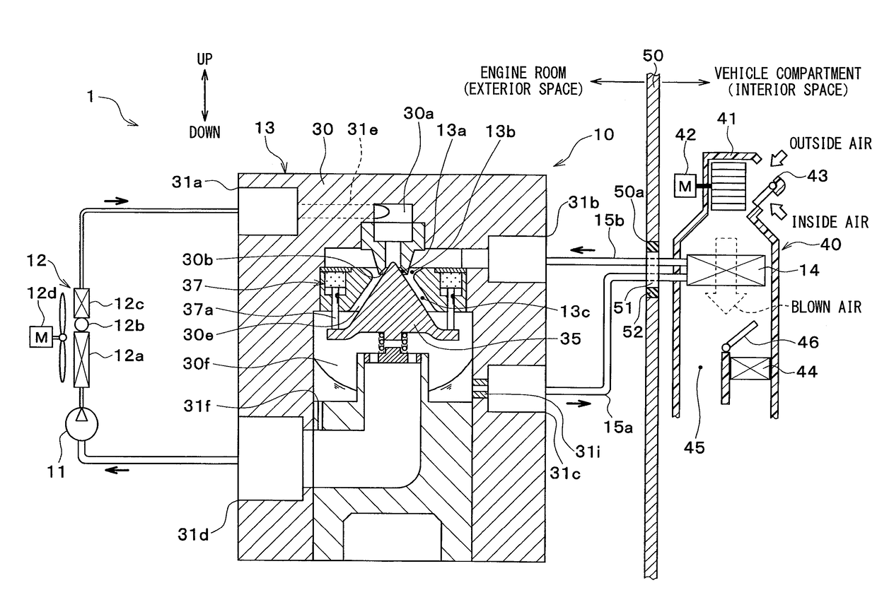
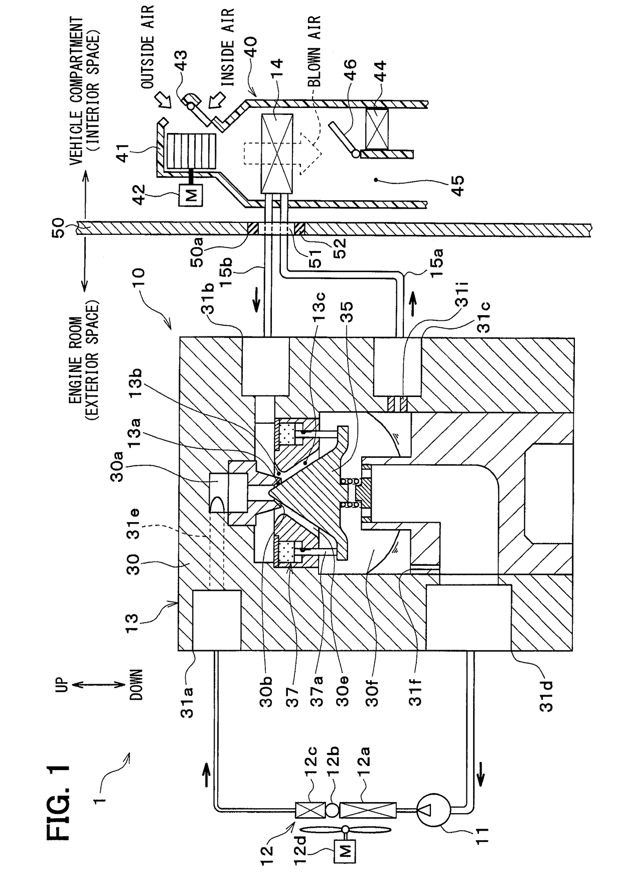
[0027]A first embodiment of the present disclosure will be described below with reference to the drawings. An ejector-type refrigeration cycle 10 of the present embodiment illustrated in an overall configuration diagram in FIG. 1 is applied to a vehicle air conditioner 1 and cools a blown air to be blown into a vehicle compartment (i.e., an interior space) which is a space to be air conditioned. Therefore, fluid to be cooled by the ejector-type refrigeration cycle 10 is the blown air.

[0028]An HFC refrigerant (specifically, R134a) is employed as refrigerant in the ejector-type refrigeration cycle 10 and the ejector-type refrigeration cycle 10 forms a subcritical refrigeration cycle in which a high-pressure side refrigerant pressure does not exceed a critical pressure. Of course, an HFO refrigerant (specifically, R1234yf) or the like may be employed as refrigerant.

[0029]Moreover, refrigerant oil is mixed into the refrigerant for lubricating a compressor 11 and a part of the refrigeran...

second embodiment

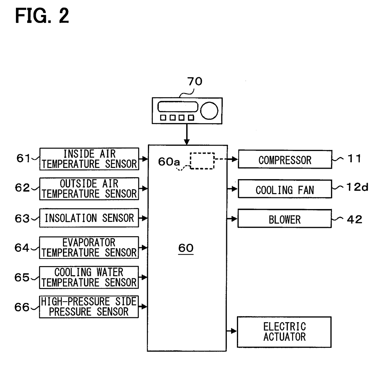
[0126]In the present embodiment, an example in which a control mode of the control section S81 forming the pressure difference determining section is changed will be described. In the control section S81 of the present embodiment, it is determined whether a low pressure difference operating condition is met by using an outside air temperature Tam detected by the outside air temperature sensor 62.

[0127]Here, during dehumidification heating operation performed at a low outside air temperature, performance required for an ejector-type refrigeration cycle 10 to cool blown air is low and a heat load on the ejector-type refrigeration cycle 10 is small. Therefore, refrigerant discharge capacity of a compressor 11 decreases and a pressure difference ΔP between a high-pressure side refrigerant pressure Pd and a low-pressure side refrigerant pressure Ps of the cycle is liable to decrease.

[0128]Therefore, in the present embodiment, as illustrated in a control characteristic diagram in FIG. 5, ...


PUM


Abstract

An ejector-type refrigeration cycle has a compressor, an ejector module, a discharge capacity control section, and a pressure difference determining section. The ejector module has a body providing a gas-liquid separating space. The pressure difference determining section determines whether a low pressure difference operating condition is met. The low pressure difference operating condition is an operating condition in which a pressure difference obtained by subtracting a low-pressure side refrigerant pressure from a high-pressure side refrigerant pressure a predetermined reference pressure difference or lower. The body is provided with an oil return passage that guides a part of a liquid-phase refrigerant to flow from the gas-liquid separating space to a suction side of the compressor. The discharge capacity control section sets a refrigerant discharge capacity to be a predetermined reference discharge capacity or higher when the low pressure difference operating condition is determined to be met.

Description

CROSS REFERENCE TO RELATED APPLICATION[0001]This application is based on Japanese Patent Application No. 2014-217454 filed on Oct. 24, 2014, the disclosure of which is incorporated herein by reference.TECHNICAL FIELD[0002]The present disclosure relates to an ejector-type refrigeration cycle including an ejector as a refrigerant pressure reducer.BACKGROUND ART[0003]Conventionally, an ejector-type refrigeration cycle that is a vapor compression refrigeration cycle is known to have an ejector as a refrigerant pressure reducer.[0004]In an ordinal refrigeration cycle, a refrigerant evaporating pressure in an evaporator is substantially equal to a pressure of a suction refrigerant drawn into a compressor. In contrast, the ejector-type refrigeration cycle increases the pressure of the suction refrigerant as compared to the ordinal refrigeration cycle. In this way, in the ejector-type refrigeration cycle, it is possible to reduce power consumed by a compressor to thereby enhance a coefficie...

Claims


Application Information

Patent Timeline
Patent Type & Authority Applications(United States)
IPC IPC(8): F25B1/06F25B41/00
CPCF25B1/06F25B2341/0014F25B41/00F25B6/04F25B49/02F25B2341/0012F25B2700/1931F25B2700/2104F25B2700/2106F25B2700/2117
Inventor KUME, MAKOTOYAMADA, MASAHIROTASHIRO, TOSHIYUKIARAKI, YOSHINORINISHIJIMA, HARUYUKINAGANO, YOUHEIYOKOYAMA, YOSHIYUKI
Owner DENSO CORP
Learn More