
Emergency operating mode for a piston engine in an airplane

a technology of emergency operating mode and piston engine, which is applied in the direction of machines/engines, electric control, instruments, etc., can solve the problems of increased maintenance costs, increased risk of loss of control, and reduced service life of aircraft components, so as to avoid the damage of defective or incorrectly operating sensors.

Inactive Publication Date: 2015-09-10
ROBERT BOSCH GMBH
View PDF29 Cites 0 Cited by
  • Summary
  • Abstract
  • Description
  • Claims
  • Application Information

AI Technical Summary

Benefits of technology

The present invention provides a simplified control system for piston engines that allows for safe and efficient operation even in the event of an emergency operating mode. The system uses fixed substitute values for operating parameters, avoiding the need for sensors and preventing sensor-related defects from affecting the engine. The system also optimizes power output by adjusting fuel pump current, valve position, propeller angle, and temperature corrections, among others. The invention also includes an emergency operating mode activation switch that allows for quick and efficient activation of the emergency mode.

Problems solved by technology

Airplane components are subject to considerable stress in operation.
Since a failure of a drive of an airplane or a failure of controls for operating the drive of the airplane during a flight represents a considerable potential risk, the European Aviation Safety Agency requires that a risk of loss of control over a respective drive unit, for example a piston engine, through a fault in a respective control system be sufficiently small.
Mechanical solutions for operating a piston engine in an airplane in the event of a malfunction have the disadvantage, however, that they require additional maintenance costs and are consequently themselves likewise susceptible to malfunctions.
Mechanical solutions furthermore offer only a limited potential for correction or adaptation to a respective failure scenario.
A failure or a drift of one or more of such sensors and / or actuators, such as a throttle valve for example, may result in a reduction of a torque or a current power output of a respective piston engine due to complex causal interdependencies.
If a fault in an engine control is not detected with sufficient precision, a danger may arise as a result.
Even if the respective fault is detected, however, it is a challenge for the respective engine control system how to deal with the detected fault.

Method used


Image

  • Emergency operating mode for a piston engine in an airplane
  • Emergency operating mode for a piston engine in an airplane

Examples


Embodiment Construction

[0030]The present invention is represented schematically in the drawings on the basis of specific embodiments and is described in detail below with reference to the drawings.

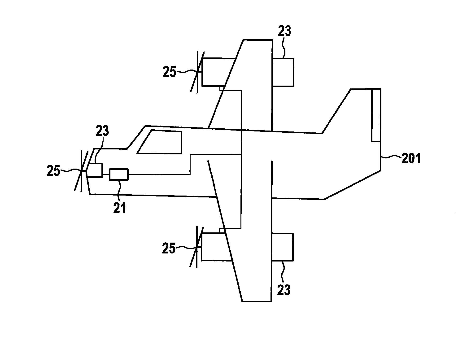
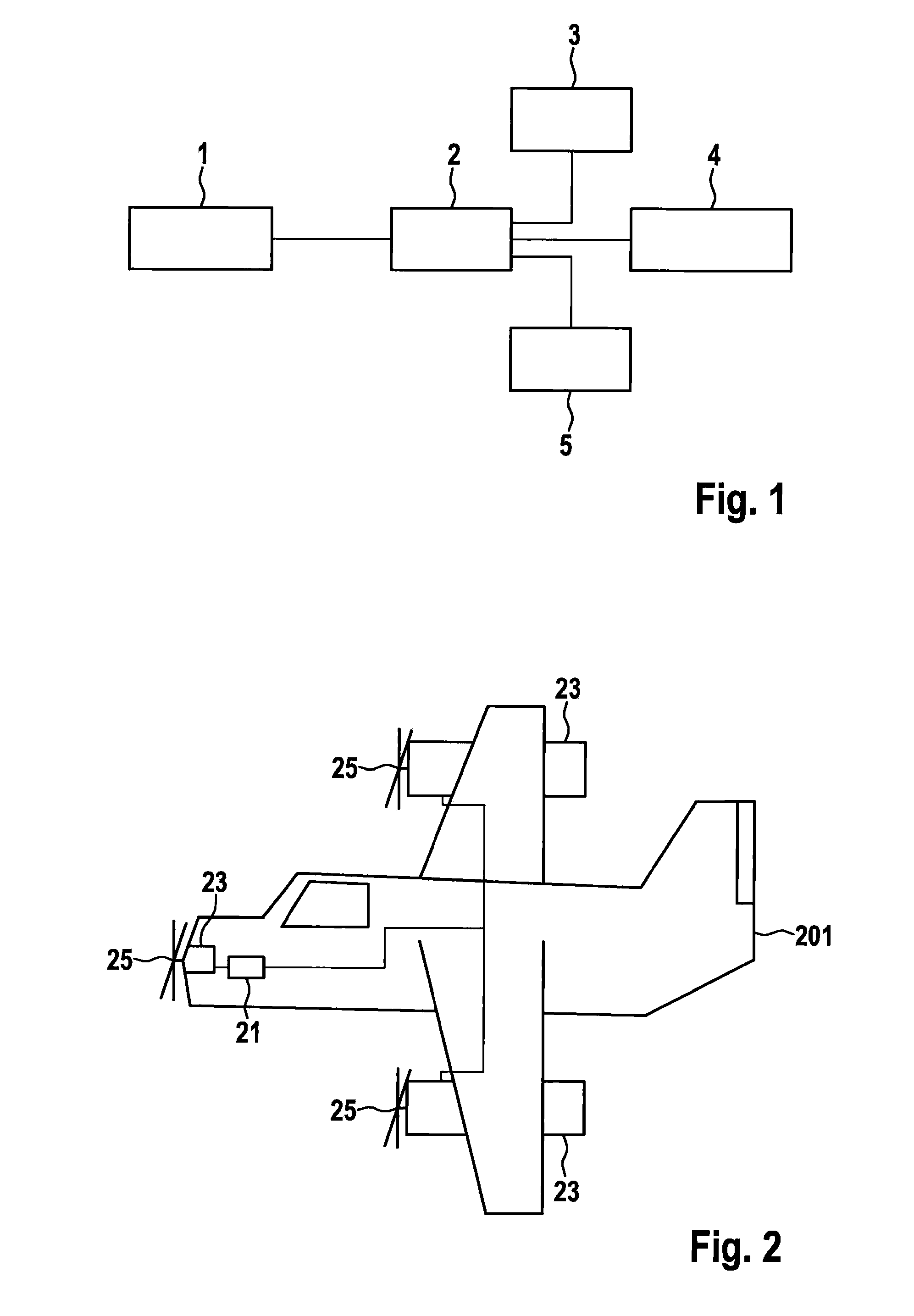
[0031]The sequence of the method of the present invention shown in FIG. 1 begins with a method step 1, in which a button is pressed for activating an emergency operating mode, whereupon an emergency operation control unit is activated in a method step 2 and normally a standard control unit is deactivated. In a method step 3, the emergency operation control unit deactivates respective sensors provided for controlling at least one piston engine of an airplane and in a method step 4 sets respective actuators provided for controlling the at least one piston engine to a firmly defined state. Furthermore, respective sensor values of the deactivated sensors are substituted with values permanently stored in the emergency operation control unit.

[0032]In a method step 5, the at least one piston engine is regulated by the ...


PUM


Abstract

A method is provided for operating a piston engine in an airplane in an emergency operating mode, in which a minimum power output of the piston engine is ensured in that an emergency operating mode is activated that is as much as possible independent of measured values of respective sensors provided for an operation of the piston engine, in which the measured values of the sensors are substituted with firmly specified values. A corresponding airplane is provided as well as to an emergency operation control unit for carrying out the provided method.

Description

BACKGROUND INFORMATION[0001]Airplane components are subject to considerable stress in operation. In particular, piston engines for driving an airplane as well as sensors required for controlling the piston engine are stressed for example by three-dimensional changes of position as well as by great temperature fluctuations during a flight.[0002]Since a failure of a drive of an airplane or a failure of controls for operating the drive of the airplane during a flight represents a considerable potential risk, the European Aviation Safety Agency requires that a risk of loss of control over a respective drive unit, for example a piston engine, through a fault in a respective control system be sufficiently small.[0003]For maintaining control or power output of a piston engine in the event of a sensor defect for example or similar scenarios that result in a loss of engine output or control over the engine output, mechanical solutions are known in the related art such as for example a use of...

Claims


Application Information

Patent Timeline
Patent Type & Authority Applications(United States)
IPC IPC(8): F02D29/02
CPCF02D29/02B64D25/00B64D37/32F02D41/22Y02T10/40F02D41/222F02D2041/227
Inventor HEYL, ANDREASDAMM, DANIELHERBORD, MARKUSWETTIG, MATTHIASFEUCHTER, WILFRIEDSOMMER, NICOLAS
Owner ROBERT BOSCH GMBH
Learn More