Drone, method for controlling flight of the same, and non-transitory computer-readable recording medium storing program
- Summary
- Abstract
- Description
- Claims
- Application Information
AI Technical Summary
Benefits of technology
Problems solved by technology
Method used
Image
Examples
first embodiment
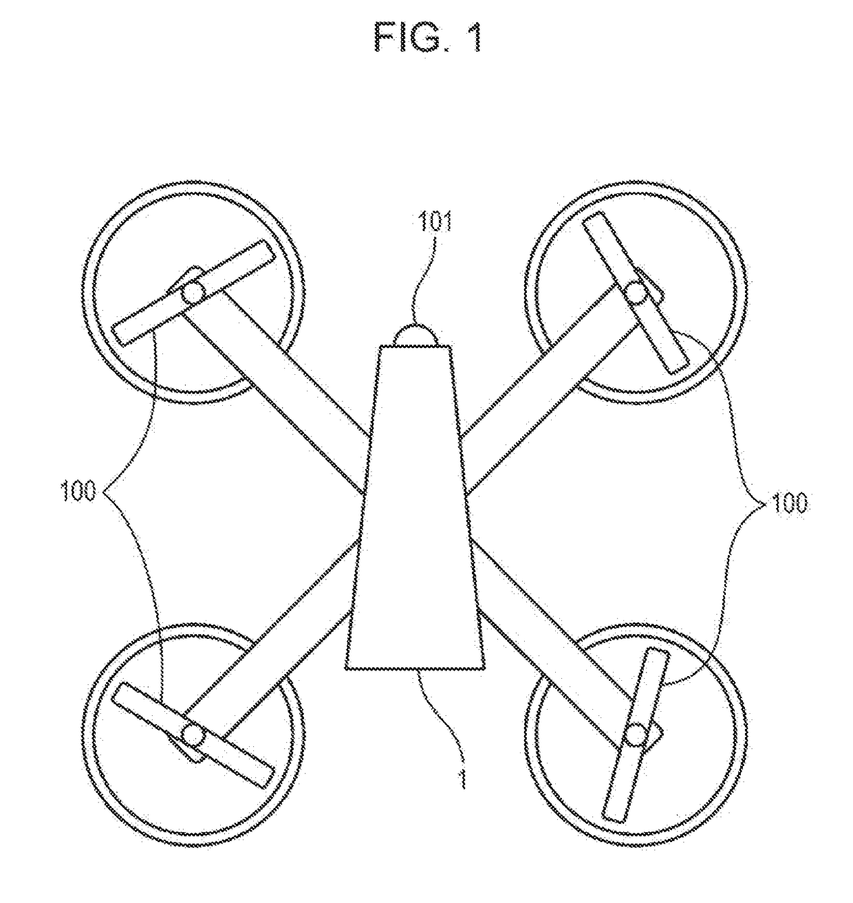
[0066]FIG. 1 is a plan view of a drone according to a first embodiment of the present disclosure.
[0067]A drone 1 illustrated in FIG. 1 is remotely controlled by an operator using a controller. The drone 1 includes a plurality of propellers 100 and can freely fly through the air. In the present embodiment, the drone 1 includes four propellers 100, but the number of propellers 100 in the present disclosure is not particularly limited to this. The drone 1 may include eight propellers, instead.
[0068]An illuminance sensor 101 is provided on a front surface of the drone 1. The illuminance sensor 101 is a phototransistor or a photodiode, for example, and detects an illuminance in a flight direction of the drone 1. A position at which the illuminance sensor 101 is provided is not limited to the front surface of the drone 1, and may be anywhere on the drone 1 insofar as the illuminance sensor 101 can detect the illuminance in the flight direction of the drone 1. Since the drone 1 can fly in ...
second embodiment
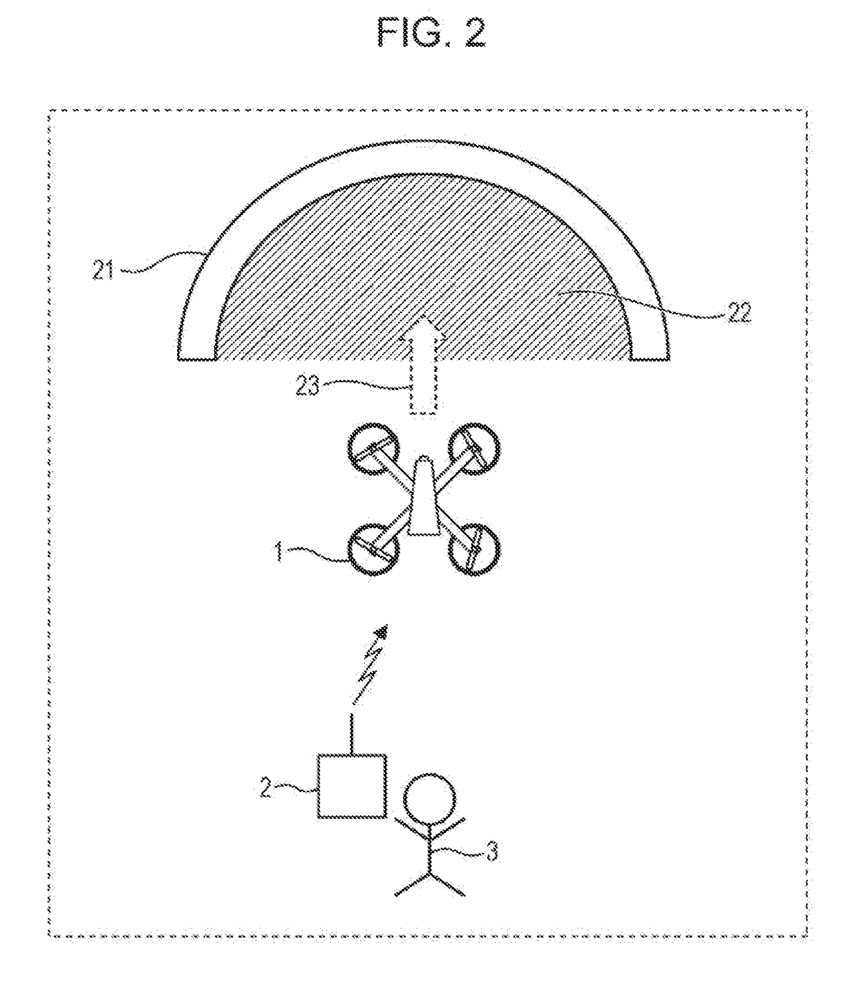
[0091]FIG. 6 is a schematic diagram illustrating the operation of a drone 1 according to a second embodiment.
[0092]In the second embodiment, if an illuminance in the flight direction 23 of the drone 1 detected by the illuminance sensor 101 on the drone 1 does not satisfy the required illuminance for the drone 1 to fly, the drone 1 is inhibited from flying in the flight direction 23. In addition, in the second embodiment of the present disclosure, if the detected illuminance does not satisfy the required illuminance, notification information indicating that the drone 1 does not fly in the flight direction 23 is transmitted to the controller 2 used by the operator 3.
[0093]The controller 2 may be, for example, a smartphone, a tablet computer, or a personal computer, instead.
[0094]FIG. 7 is a block diagram illustrating the configuration of the drone 1 according to the second embodiment of the present disclosure. The drone 1 illustrated in FIG. 7 includes the illuminance sensor 101, the ...
third embodiment
[0110]FIG. 11 is a schematic diagram illustrating the operation of a drone 1 according to a third embodiment.
[0111]In the third embodiment, if an illuminance in the flight direction of the drone 1 detected by the illuminance sensor 101 on the drone 1 does not satisfy the required illuminance for the drone 1 to fly, the drone 1 is inhibited from flying in the flight direction. In addition, in the third embodiment, if the detected illuminance does not satisfy the required illuminance, the drone 1 flies in a direction different from the flight direction.
[0112]As illustrated in FIG. 11, if a detected illuminance does not satisfy the required illuminance, the drone 1 automatically turns around in a direction indicated by an arrow 24.
[0113]FIG. 12 is a block diagram illustrating the configuration of the drone 1 according to the third embodiment of the present disclosure. The drone 1 illustrated in FIG. 12 includes the illuminance sensor 101, the gyro sensor 102, the driving unit 103, the ...
PUM
 Abstract
Description
Claims
Application Information
 - R&D
- Intellectual Property
- Life Sciences
- Materials
- Tech Scout
- Unparalleled Data Quality
- Higher Quality Content
- 60% Fewer Hallucinations
Browse by: Latest US Patents, China's latest patents, Technical Efficacy Thesaurus, Application Domain, Technology Topic, Popular Technical Reports.
© 2025 PatSnap. All rights reserved.Legal|Privacy policy|Modern Slavery Act Transparency Statement|Sitemap|About US| Contact US: help@patsnap.com


