System and method for controlling flow of cooling air in battery system

Active Publication Date: 2017-10-19
LG ENERGY SOLUTION LTD
View PDF102 Cites 10 Cited by
  • Summary
  • Abstract
  • Description
  • Claims
  • Application Information

AI Technical Summary

Benefits of technology

[0030]According to one aspect of the present invention, it is possible to provide a system and a method for controlling a flow of cooling air in a battery system, in which a pipe connected to an outlet discharging cooling air of an air conditioning system and forming a flow path of the cooling air is included, and the pipe includes a plurality of module cooling ports corresponding to a plurality of battery modules, respectively, and makes the cooling air pass through each battery module through each module cooling port to cool the plurality of battery modules, so that it is possible to minimize the loss of coldness of the cooling air and supply the cooling air to each battery module, thereby decreasing the amount of energy consumed by the air conditioning system in order to maintain a constant temperature of the battery system. Further, it is possible to provide the system and the method for controlling a flow of cooling air i

Problems solved by technology

The temperature deviation between the battery modules according to a position in the general air conditioning system in the related art generally exerts a bad effect to two parts.
Accordingly, when the battery system fails to rapidly adjust the temperature deviation, so that the temperature deviation between the battery modules of the battery system exceeds the predetermined level, the temperature deviation diagnosis function

Method used


Image

  • System and method for controlling flow of cooling air in battery system
  • System and method for controlling flow of cooling air in battery system
  • System and method for controlling flow of cooling air in battery system

Examples


Embodiment Construction

Technical Problem

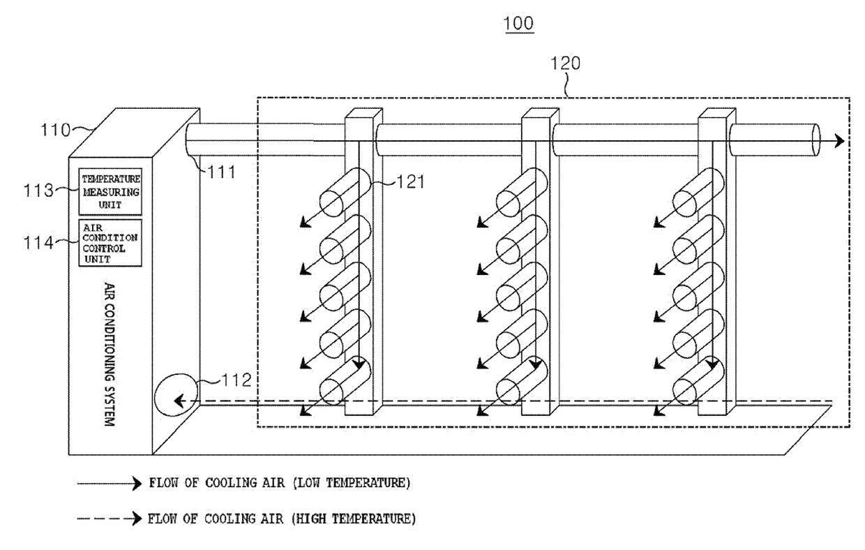
[0009]An object of the present invention is to provide a system and a method for controlling a flow of cooling air in a battery system, in which a pipe connected to an outlet discharging cooling air of an air conditioning system and forming a flow path of the cooling air is included, and the pipe includes a plurality of module cooling ports corresponding to a plurality of battery modules, respectively, and makes the cooling air pass through each battery module through each module cooling port to cool the plurality of battery modules, so that it is possible to minimize the loss of coldness of the cooling air and supply the cooling air to each battery module, thereby decreasing the amount of energy consumed by the air conditioning system in order to maintain a constant temperature of the battery system. Another object of the present invention is to provide a system and a method for controlling a flow of cooling air in a battery system, in which it is not necessary to ...


PUM


Abstract

The system for controlling a flow of cooling air in a battery system for cooling the battery system according to the present invention includes: an air conditioning system which includes an outlet discharging cooling air for reducing a temperature of the plurality of battery modules, and an inlet taking in cooling air, of which a temperature is increased, after reducing the temperature of the plurality of battery modules; and a pipe which includes a plurality of module cooling ports connected to the outlet, forming a flow path of the cooling air, and corresponding to the plurality of battery modules, respectively, and makes the cooling air discharged through the outlet pass through each battery module through each module cooling port to cool the plurality of battery modules.

Description

TECHNICAL FIELD[0001]This application claims priority to and the benefit of Korean Patent Application No. 10-2014-0143658 filed in the Korean Intellectual Property Office on Oct. 22, 2014, the entire contents of which are incorporated herein by reference.[0002]The present invention relates to a system and a method for controlling a flow of cooling air in a battery system, which cool a battery system including a plurality of battery modules, and more particularly, to a system and a method for controlling a flow of cooling air in a battery system, in which a pipe connected to an outlet discharging cooling air of an air conditioning system and forming a flow path of the cooling air is included, and the pipe includes a plurality of module cooling ports corresponding to a plurality of battery modules, respectively, and makes the cooling air pass through each battery module through each module cooling port to cool the plurality of battery modules, so that it is possible to minimize the lo...

Claims


Application Information

Patent Timeline
IPC IPC(8): H01M10/63H01M10/6556H01M10/6563H01M10/6566
CPCH01M10/63H01M10/6566H01M10/6563H01M10/6556H01M10/486H01M10/6561H01M10/627Y02E60/10H01M10/613
Inventor KIM, JIHUN
Owner LG ENERGY SOLUTION LTD
Why Eureka
Try Eureka