Low profile antenna module

a low-profile, antenna technology, applied in the direction of antennas, antenna details, antenna earthings, etc., can solve the problems of antennas introducing a trip hazard, m2m applications can be demanding, ground level, etc., to achieve the effect of reducing frequency shi

Active Publication Date: 2017-10-19
KYOCERA AVX COMPONENTS (SAN DIEGO) INC
View PDF5 Cites 5 Cited by
  • Summary
  • Abstract
  • Description
  • Claims
  • Application Information

AI Technical Summary

Problems solved by technology

Some M2M applications can be demanding when a low profile antenna is required, specifically when the height allocated for the antenna is not sufficient for efficient operation at the required frequency.
If the antenna is operating at an industrial scientific and medical (ISM) frequency band such as, for example, 434 MHz or 915 MHz, the height required for efficient antenna operation when placed at ground level might be such that the antenna introduces a trip hazard.
Many of the commercial wireless applications, such as M2M and IoT applications, require an antenna to transmit or receive equally well over wide fields of view since there could be motion involved in the application or a lack of consistency in communication system architecture such that the placement of communication nodes varies from one installation to the next.
When a low profile antenna module is required, and the frequency of operation is such that the height or thickness allowed for the antenna module is a fraction of a wavelength, it will be difficult to achieve uniform radiation pattern coverage in a plane of the antenna that is normal to the axis aligned with the dimension of reduced height.
Additionally it will be difficult to achieve uniform pattern coverage in the plane normal to the axis aligned with the dimension of reduced height when the polarization of the antenna is required to align with the axis normal to the dimension of reduced height.
For example it will be difficult to design an antenna module with vertical polarization referenced to the ground when the antenna is required to be placed on the ground, especially when uniform coverage is required in the plane of the antenna.

Method used


Image

  • Low profile antenna module
  • Low profile antenna module
  • Low profile antenna module

Examples


Embodiment Construction

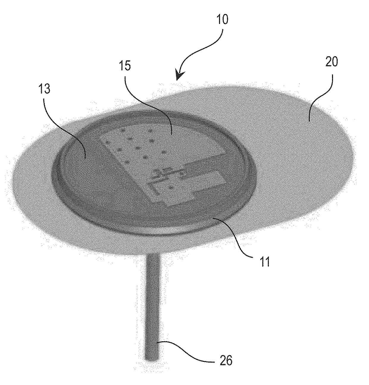
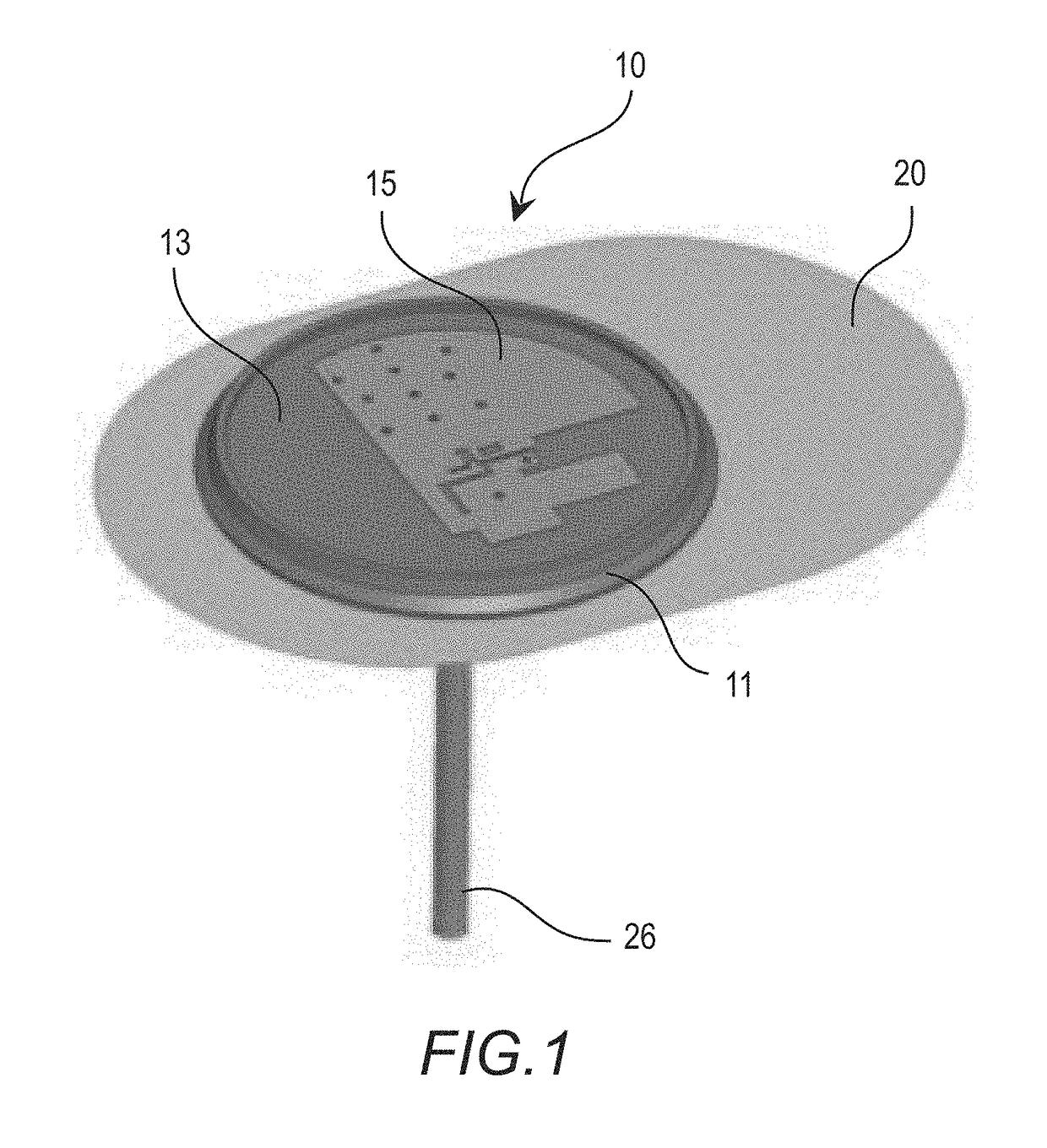
[0023]The following describes an antenna module for low profile (reduced height) applications where uniform radiation pattern coverage can be achieved over a wide angular field of view. The polarization can be aligned with the reduced height dimension to provide vertical polarization when the antenna is positioned on the ground.

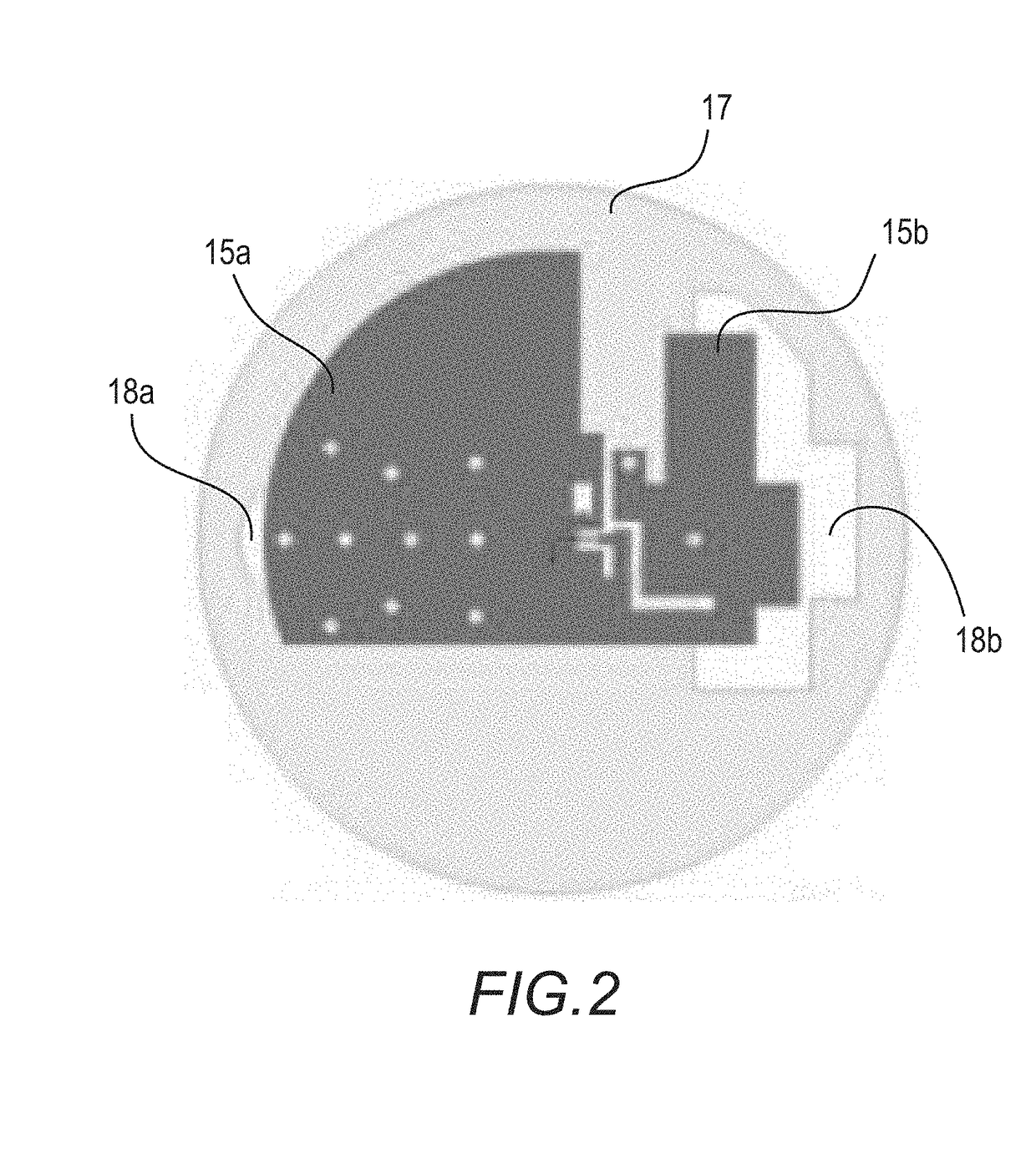
[0024]In particular, an antenna module is described where omni-directional radiation pattern performance is achieved with the dominant polarization being normal to the plane that contains the dominant two dimensions of the antenna in a reduced height form factor. A ground plane aperture is disclosed wherein a frequency response of the antenna does not shift as the antenna is moved from a conductive ground plane to a non-conductive ground plane, for example, integration with a utility meter (water meter) having a plastic support structure or housing vs. one with a metallic support structure or housing. The antenna module as disclosed herein is ideal for applic...


PUM


Abstract

An antenna module is described where uniform radiation pattern coverage is provided in the plane of a low profile antenna radiating element. A polarization that is orthogonal to the plane of the low profile antenna radiating element can be achieved for the radiated field. A ground plate aperture is implemented into the antenna ground plate to minimize frequency shift as the antenna is installed on metallic (conductive) and non-metallic (non-conductive) ground planes of varying sizes. This antenna system technique is applicable for use in communication systems such as a local Area network (LAN), cellular communication network, and Machine to Machine (M2M).

Description

CROSS-REFERENCE TO RELATED APPLICATIONS[0001]This application claims benefit of U.S. Provisional Ser. No. 62 / 324,221, filed Apr. 18, 2016, titled “LOW PROFILE ANTENNA SYSTEM”; the entire contents of which are hereby incorporated by reference.BACKGROUND OF THE INVENTIONField of the Invention[0002]This invention relates generally to the field of wireless communication. In particular, the invention relates to an antenna module configured to provide low profile attributes with uniform radiation pattern coverage in the plane of the antenna radiating element associated with the module.Description of the Related Art[0003]A proliferation of wireless communication systems such as wireless wide area networks (WWANs) also referred to as “cellular systems”, wireless local area networks (WLANs), machine to machine (M2M) systems, and internet of things (IoT) applications, has increased the number and types of devices and infrastructure that antennas are, or will, need to be designed into and / or i...

Claims


Application Information

Patent Timeline
Patent Type & Authority Applications(United States)
IPC IPC(8): H01Q9/04H01Q1/48H01Q1/22
CPCH01Q9/0407H01Q1/2233H01Q1/48H01Q1/36H01Q1/2291H01Q1/38
Inventor DESCLOS, LAURENT
Owner KYOCERA AVX COMPONENTS (SAN DIEGO) INC
Why Eureka
Try Eureka