Eureka AIR delivers breakthrough ideas for toughest innovation challenges, trusted by R&D personnel around the world.

Blade for centrifugal blast wheel machine and method of maintaining a centrifugal blast wheel machine

Active Publication Date: 2017-10-26
WHEELABRATOR GRP
View PDF1 Cites 0 Cited by
  • Summary
  • Abstract
  • Description
  • Claims
  • Application Information

AI Technical Summary

Benefits of technology

The patent text describes a centrifugal blast wheel machine that includes a housing and a wheel assembly with blades that throw blast media against a work piece. The blades have a curved portion and a straight portion, with the first edge of the blade forming a angle of between 105° and 145° with the central hub of the wheel assembly. The blades also have a recess and a grommet positioned in the recess. The machine also includes a method for maintaining it. The technical effects of the invention include improved blasting efficiency, reduced noise, and improved safety.

Problems solved by technology

Operating and properly maintaining a blast wheel can incur multiple ongoing expenses.
For example, a cost associated with supplying blast media is one such expense.
Another example is a cost associated with maintaining the blast wheel by replacing blades that have become worn down.

Method used


Image

  • Blade for centrifugal blast wheel machine and method of maintaining a centrifugal blast wheel machine
  • Blade for centrifugal blast wheel machine and method of maintaining a centrifugal blast wheel machine
  • Blade for centrifugal blast wheel machine and method of maintaining a centrifugal blast wheel machine

Examples


Embodiment Construction

[0023]For the purposes of illustration only, and not to limit the generality, the present disclosure will now be described in detail with reference to the accompanying figures. This disclosure is not limited in its application to the details of construction and the arrangement of components set forth in the following description or illustrated in the drawings. The principles set forth in this disclosure are capable of other embodiments and of being practiced or carried out in various ways. Also the phraseology and terminology used herein is for the purpose of description and should not be regarded as limiting. The use of “including,”“comprising,”“having,”“containing,”“involving,” and variations thereof herein, is meant to encompass the items listed thereafter and equivalents thereof as well as additional items.

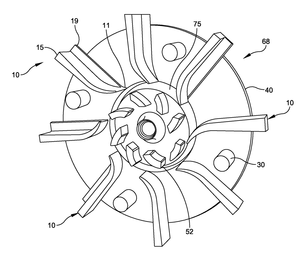
[0024]The present disclosure is directed blades for a centrifugal blast wheel machine. Specifically, the present disclosure is directed to blades designed to facilitate safer ...


PUM


Abstract

A centrifugal blast wheel machine comprises a housing and a wheel assembly coupled to the housing. The wheel assembly has a plurality of blades configured to throw blast media introduced into the wheel assembly against a work piece. According to one embodiment, each blade of the plurality of blades includes a curved portion positioned adjacent a central hub of the wheel assembly, and a straight portion integrally formed with the curved portion extending radially outwardly from the wheel assembly. According to another embodiment, each blade includes a first side rail extending along the blade, the first side rail having a first recess, and a first grommet positioned in the first recess.

Description

BACKGROUND OF THE DISCLOSURE1. Field of the Disclosure[0001]The present disclosure relates generally to centrifugal blast wheel machines, and more particularly to blades for a centrifugal blast wheel machine and to methods of maintaining a centrifugal blast wheel machine.2. Discussion of Related Art[0002]Centrifugal blast wheel machines generally include a rotatable hub to which is mounted a disk or a pair of spaced disks which carry radially extending blades. Particulate matter is discharged from a center of the wheel disk onto rotating surfaces of the blades, which propel the particulate matter against surfaces of a work piece to be cleaned or treated. Specifically, blast media is fed from a feed spout into a rotating impeller situated within a control cage at the center of the blast wheel. The media is fed from the impeller, through an opening in a control cage and onto leading edges of the rotating blades. The media travels along top surfaces of the blades and is thrown from tra...

Claims


Application Information

Patent Timeline
IPC IPC(8): B24C5/06
CPCB24C5/06B24C5/062
Inventor BITZEL, JR., RAYMOND PAULREAVES, MICHAEL DWAYNEBAER, CHRISTOPHWEISSENBERGER, PHILIPPWRUCK, JURGEN
Owner WHEELABRATOR GRP
Why Eureka
Eureka Blog
Learn More