Hydraulic Whipstock Anchor

Inactive Publication Date: 2017-10-26
BAKER HUGHES INC
View PDF5 Cites 10 Cited by
  • Summary
  • Abstract
  • Description
  • Claims
  • Application Information

AI Technical Summary

Problems solved by technology

Release occurs with a pull induced component failure that relieves hydraulic pressure that allows the slips to retract.

Method used


Image

  • Hydraulic Whipstock Anchor
  • Hydraulic Whipstock Anchor
  • Hydraulic Whipstock Anchor

Examples


Embodiment Construction

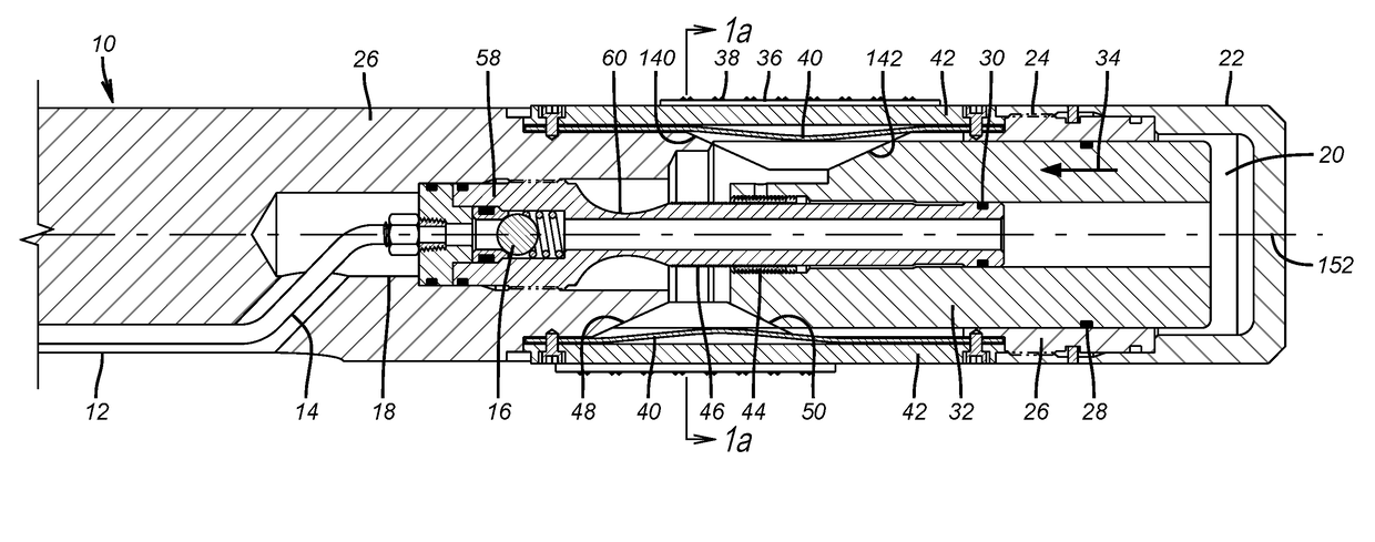
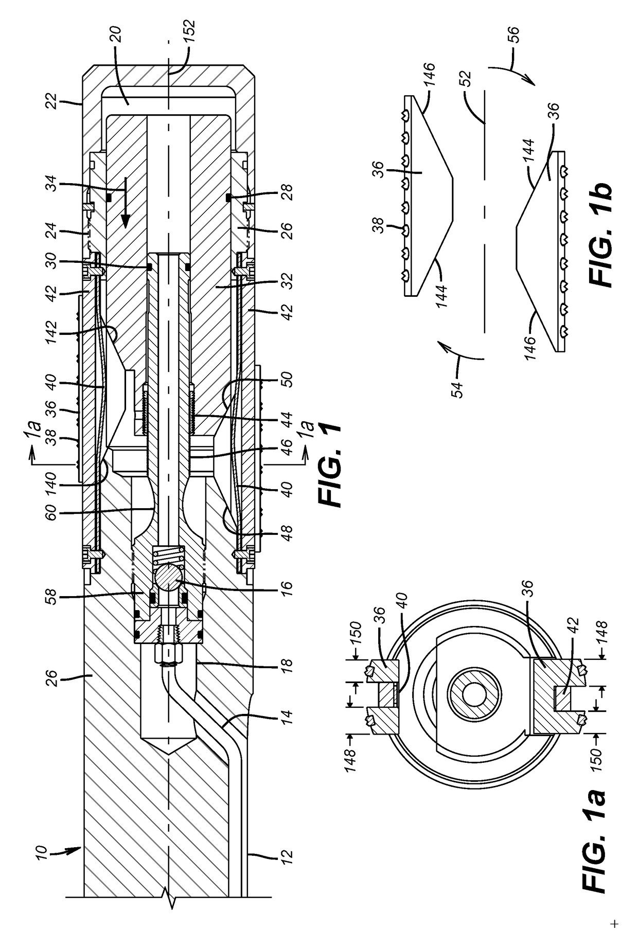
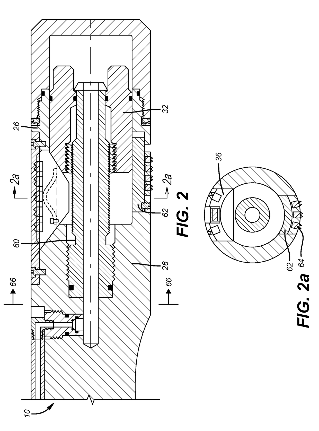
[0022]Referring to FIG. 1, a whipstock 10 has a ramp 12 and an associated hydraulic line 14 that typically is run behind the ramp 12 to protect the line 14 from the advancing window mill that is not shown. A check valve 16 in line 14 allows flow one way into passage 18 to chamber 20 defined by cap 22 secured at thread 24 to housing 26. Cone 32 is sealed with seals 28 and 30 so that built up pressure in chamber 20 moves cone 32 in the direction of arrow 34 toward the housing 26. Two slips 36 are shown at 180 degree spacing although different spacing and number of slips is contemplated. The slips 36 have external carbide or hardened inserts 38 to dig into the surrounding tubular that is not shown to support the whipstock 10. A biasing spring 40 pushes between a respective slip 36 and a retainer 42 that limits the outward travel of each slip 36. A lock ring 44 is moved along ratchet profile 46 as cone 32 moves in the direction of arrow 34 to prevent reverse movement of the cone 32. The...


PUM


Abstract

A whipstock anchor is hydraulically set and locked in the set position. Release occurs with a pull induced component failure that relieves hydraulic pressure that allows the slips to retract. Release can occur with a remotely actuated circuit that burns a retainer for a piston whose movement opens a vent or initiates a chemical reaction to undermine a lock ring. Movement of a single cone or opposed cones extends the slips. The cone angles being different (cone angles do not have to be different, it is preferred to have the slip angles different) adds a skew to the slips and positions the top of the whipstock against the tubular top in a horizontal run. A bottom cap is removable to convert to setting by set down weight or to attach a hydraulically operated packer below the slips. Slips can be extended with radial movement of pistons.

Description

FIELD OF THE INVENTION[0001]The field of the invention is hydraulic anchor assemblies for whipstocks in borehole use and more particularly anchors that release in a variety of ways, or cock the whipstock or that can be modularly built to optionally add setting capability with setting down weight or be reconfigured to add a hydraulically actuated sealing functionality to the anchor.BACKGROUND OF THE INVENTION[0002]Whipstocks are long tapered ramps that are secured in a tubular string to guide a mill assembly laterally to make an exit through the tubular wall for the start of a lateral bore. The taper angle is gradual, in the order of about 1-3 degrees. The ramp is typically oriented with a bottom hole assembly so that the ramp faces the direction of the desired lateral. In some instances there can be a need to have the lateral exit in a downward direction off a horizontal bore. In such cases it is advantageous to ensure that the top of the whipstock is pushed against the top of the h...

Claims


Application Information

Patent Timeline
Patent Type & Authority Applications(United States)
IPC IPC(8): E21B23/01E21B34/06E21B29/06
CPCE21B23/01E21B34/06E21B29/06E21B7/061
Inventor HERN, GREGORY L.HERED, WILLIAM A.CULLUM, JASON L.
Owner BAKER HUGHES INC
Why Eureka
Try Eureka