Electrical box, electrical switch & electrical plug-in mechanism

a technology of electrical switch and plug-in, which is applied in the direction of coupling protective earth/shielding arrangement, electrical device connection, electrical apparatus, etc., can solve the problems of increasing the risk of electrical shock to the user/installer, increasing the installation time, and increasing the installation difficulty. , to achieve the effect of reducing installation time, increasing safety to/for user/installer, and reducing difficulty

Inactive Publication Date: 2017-10-26
DEROUSSE WELDA WILLIAM
View PDF18 Cites 23 Cited by
  • Summary
  • Abstract
  • Description
  • Claims
  • Application Information

AI Technical Summary

Benefits of technology

[0011]The newly improved electrical box, electrical switch and electrical plug-in mechanism is more user / installer friendly, which reduces installation time and in return reduces the difficulty and increases safety to / for user / installer installing / replacing electrical boxes, electrical switches or electrical plug-ins.
[0012]In brief, an improved electrical box, electrical switch and electrical plug-in mechanism design allows the user / installer to install / replace an electrical switch or an electrical plug-in, reducing exposure to the existing electrical wires, increasing safety to the user / installer during installation, while reducing / decreasing, risk of shock and / or death. Thus making the installation / replacement of an electrical box, electrical plug-in or electrical switch safe, fast and easy for the user / installer.

Problems solved by technology

Current installations of electrical boxes with electrical switches or electrical plug-ins are unsafe to the user / installer via existing electrical box design(s), fastened by screw(s) and exposed wires to the user / installer.
Conventional electrical boxes consist of exposed electrical wiring connections, increasing the risk of electrical shock to the user / installer, improvements to an electrical box allows the user / installer to complete the wiring connection inside of the electrical box with socket head receptacle fastening set screws.
Conventional electrical switches and / or electrical plug-ins are unsafe to the user / installer, current electrical switches and / or electrical plug-ins are supplied with fastening screws, which increases installation time and in return exposing electrical wiring to the user / installer during installation.

Method used


Image

  • Electrical box, electrical switch & electrical plug-in mechanism
  • Electrical box, electrical switch & electrical plug-in mechanism
  • Electrical box, electrical switch & electrical plug-in mechanism

Examples


Embodiment Construction

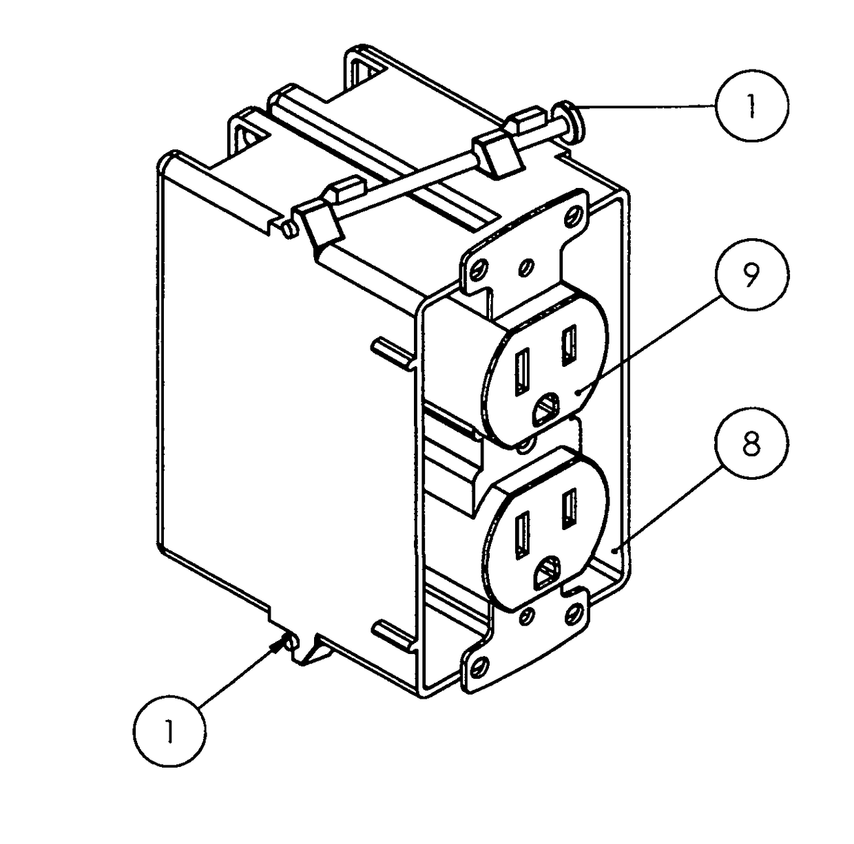
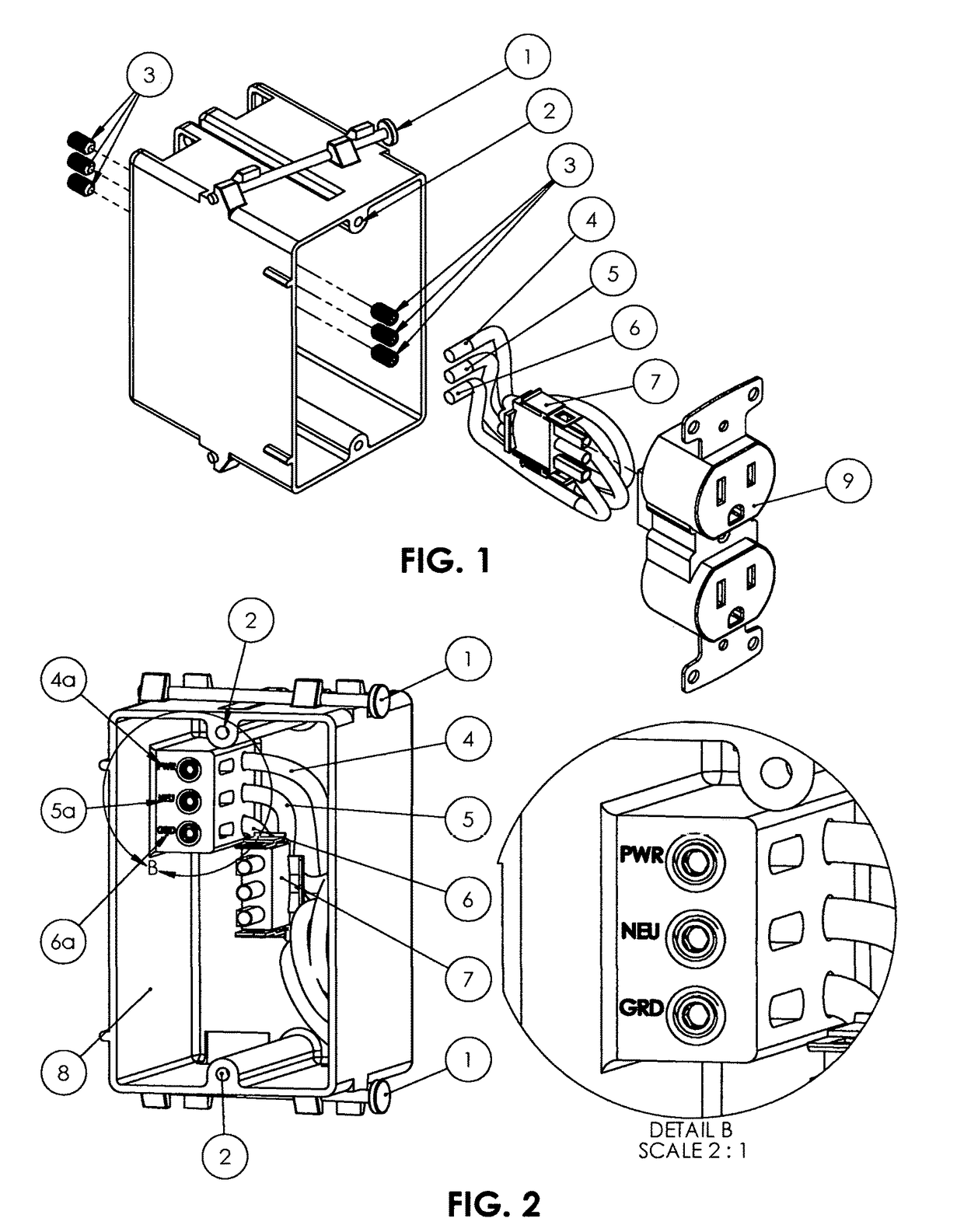
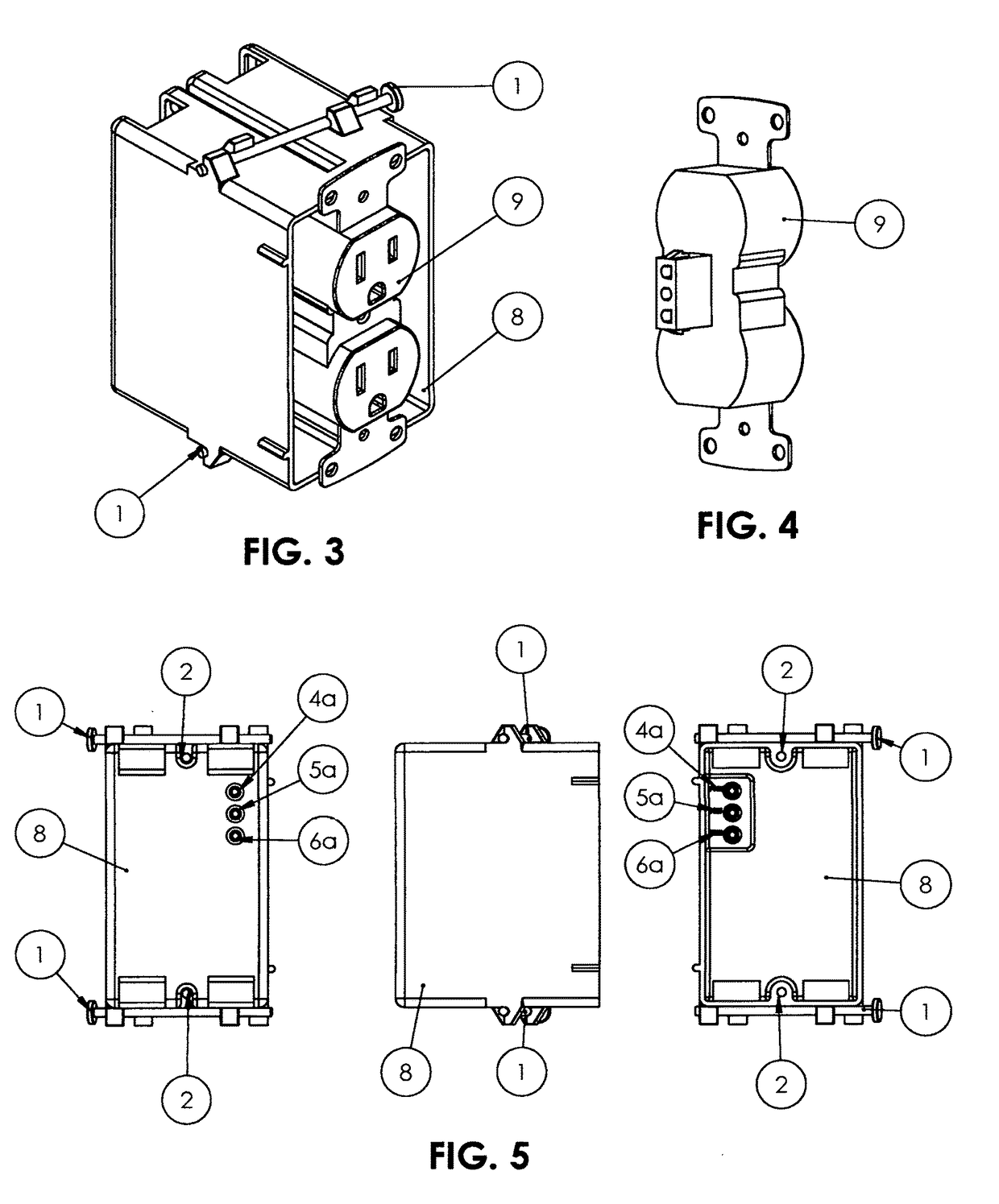
[0019]Turning to FIG. 1, an electrical box, electrical switch and electrical plug-in in accordance with the current invention, is illustrated. Electrical box, electrical switch and electrical plug-in references a 16d 3¼″ bright common framing nail 1 for attaching an electrical box 8 with installation of an electrical box 8. An electrical box 8 further includes a electrical switch / plug-in wallplate aperturere 2 to install / attach a wallplate a electrical switch and plug-in 9. Further referencing an electrical box 8 includes a power crimp housing plug 7 for quick and easy installation / replacement of an electrical switch and electrical plug-in 9. A power crimp housing plug 7 (male electrical wiring connection) includes a power / power in electrical wire 4, neutral / power out electrical wire 5 and a ground electrical wire 6, which connects to a power connector header 9 (female electrical connection) completing the electrical connection between a power crimp housing plug 7 and a power connec...


PUM


Abstract

The electrical box, switch and plug-in mechanism is an revolutionary improved electrical box design, which the newly improved design of the electrical box facilitates prompt and safe installation of the newly designed electrical box, providing ease of installation to the user / installer. The newly improved electrical box, provides a more user / installer friendly environment, reducing installation time and reducing difficulty and / or installment of the electrical box, electrical switches and electrical plug-ins. Which in turn increases safety to the user / installer with replacement of electrical switches, electrical plug-ins and / or electrical boxes. Replacement of existing electrical boxes with the newly improved electrical box design allows the user / installer to easily and quickly replace electrical switch(s) and / or electrical plug-in(s) without touching / interfacing with electrical wiring within the improved electrical box plug-in type design. The newly improved electrical box contains electrical terminals for connection of electrical quick connect plug-in(s) allowing the installer to install / connect the electrical switch(s) or electrical plug-in(s) or other mechanical devices within the electrical box finalizing the electrical circuit connection. Installation of the electrical box plug-in type design increases safety to the user / installer when installing / connecting an electrical switch(s) or electrical plug-in(s), providing safety, quick and easy installation to the user / installer.Improvements of the newly designed electrical box will not alter operation of current electrical switch(s) and / or electrical plug-in(s), the electrical box reduces exposure to electrical wiring within the electrical box increasing safety to the user / installer. Connectibility of the electrical wiring to the newly designed electrical box eliminates exposure to electrical wiring protecticting the user / installer when installing / connecting electrical switche(s) or electrical plug-in(s) to the electrical box.Specific design features / improvements are incorporated into the electrical box are unlike the design of conventional electrical boxes. Design features and improvements include: male / female electrical wire receptacle terminals, labeled electrical wiring receptacle terminals, socket head receptacle fastening set screws and threaded electrical wiring

Description

CROSS REFERENCE TO RELATED APPLICATIONS[0001]This application claims the benefit of U.S. Provisional Patent Application No. 62 / 391,123, filed Apr. 21, 2016.[0002]Field of classification search (174 / 50; 174 / 53; 174 / 59; 174 / 66; 174 / 520; 200 / 315; 307 / 112; 315 / 360; 361 / 42; 361 / 807; 439 / 136; 439 / 521; 439 / 535; 439 / 539; 439 / 625) International classification (B23P 11 / 00; B23P 17 / 00; B602 1 / 00; H05B 33 / 0845; H01H 1 / 36; H01H 3 / 38; H01H 9 / 02; H01H 21 / 02; H01H 21 / 025; H01H 23 / 16; H01H 33 / 72; H01H 33 / 182; H01H 47 / 00; H01H 47 / 22; H01H 50 / 16; H02B 1 / 24; H02G 3 / 08; H02G 3 / 10; H02G 3 / 12; H02G 3 / 14; H02G 3 / 18; H02G 3 / 086; 4 / 42; H05K 5 / 00; H05K 5 / 03; H05K 13 / 00; H05K 5 / 02; H05K 7 / 04; H05K 5 / 0217; H01R 4 / 42; H01R 13 / 58; H01R 13 / 60; H01R 13 / 66; H01R 13 / 73; H01R 13 / 74; H01R 13 / 514; H01R 13 / 703; H01R 13 / 748; H01R 13 / 6675; H01R 25 / 00; H01R 25 / 006; HR01R 13 / 154; H04N 7 / 188; G08B 13 / 24; G08B 13 / 196; G11C 11 / 419) U.S. classification CPC (B602 1 / 00; F21V 23 / 00; F21V 23 / 001; F21V 23 / 02; F21V 23 / 04; F21V 23 / 023;...

Claims


Application Information

Patent Timeline
Patent Type & Authority Applications(United States)
IPC IPC(8): H01R13/639H02G3/16H02G3/14H01R25/00H01R13/652H02G3/18H01R13/645
CPCH01R13/6395H01R13/6456H02G3/14H01R25/006H02G3/18H01R13/652H02G3/16
Inventor DEROUSSE, WELDA WILLIAM
Owner DEROUSSE WELDA WILLIAM
Why Eureka
Try Eureka