Thermal control within an enclosure with circular cross-section

Active Publication Date: 2017-10-26
HANON SYST
View PDF14 Cites 1 Cited by
  • Summary
  • Abstract
  • Description
  • Claims
  • Application Information

AI Technical Summary

Benefits of technology

The present invention provides a thermal control system for an enclosure that minimizes the negative impact on the enclosure and its contents while optimizing heating and cooling. This system is particularly useful for enclosures with a circular cross-section.

Problems solved by technology

However, it is often difficult to provide heating and cooling to the thermal masses within the sealed enclosure without causing undesired effects to the thermal masses or to the enclosures.
For example, certain materials and fluids may not be appropriate for use for cooling and heating within the enclosure due to the sensitivity of the thermal masses.

Method used


Image

  • Thermal control within an enclosure with circular cross-section
  • Thermal control within an enclosure with circular cross-section
  • Thermal control within an enclosure with circular cross-section

Examples


Embodiment Construction

[0017]The following detailed description and appended drawings describe and illustrate various exemplary embodiments of the invention. The description and drawings serve to enable one skilled in the art to make and use the invention, and are not intended to limit the scope of the invention in any manner.

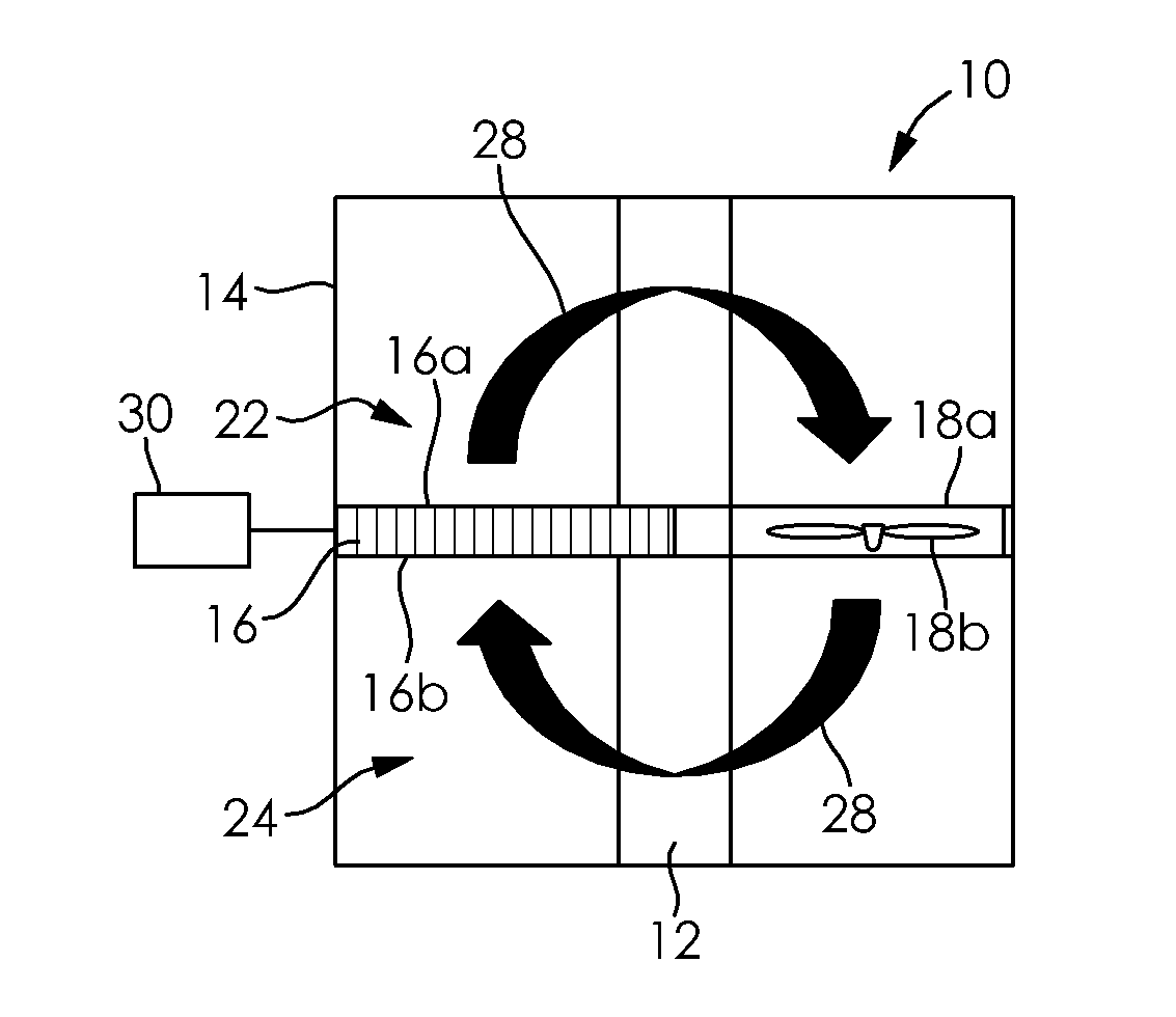
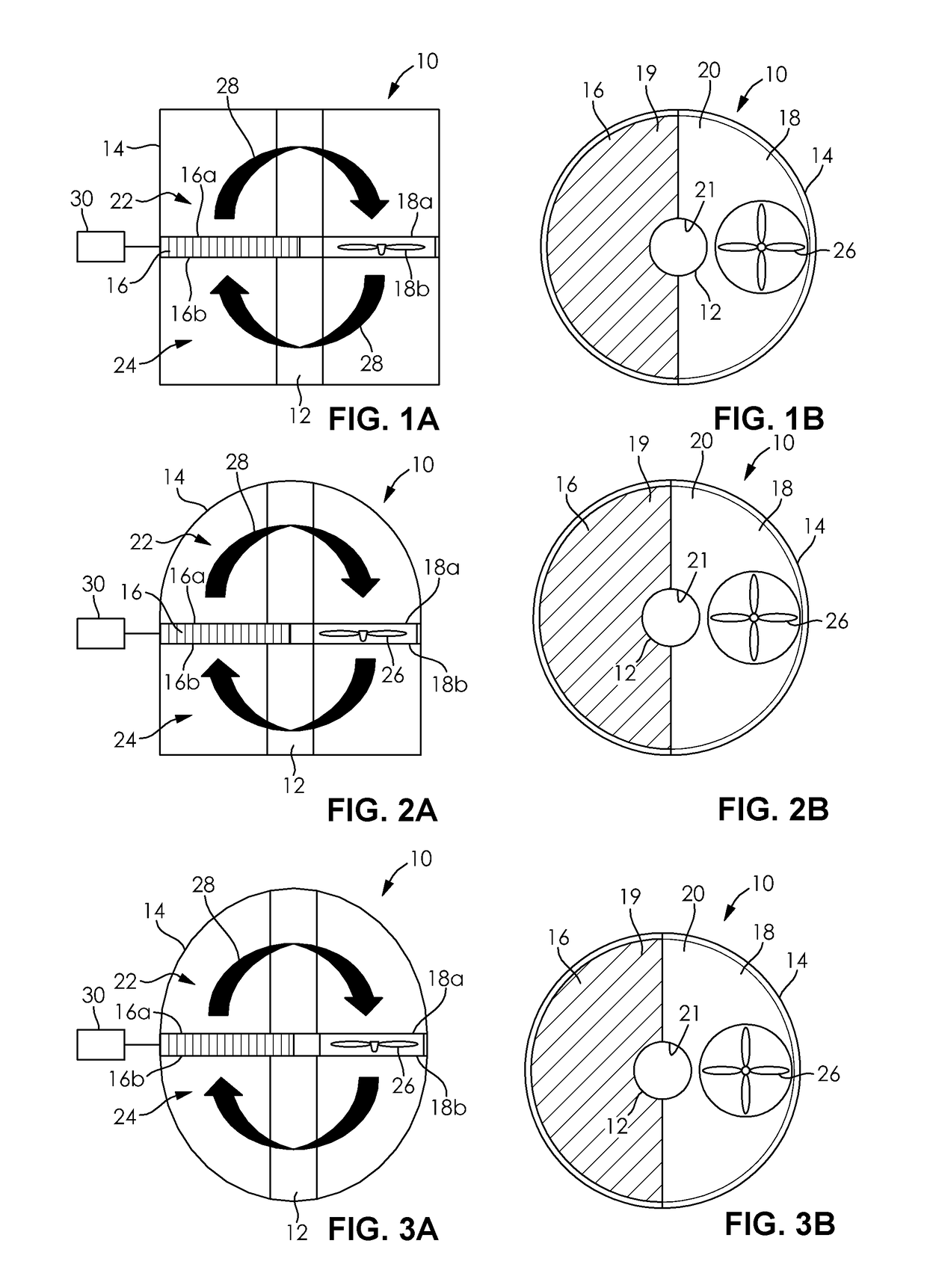
[0018]FIGS. 1A and 1B illustrate a thermal control system 10 for heating and cooling a thermal mass 12. The thermal mass 12 can be any solid, liquid, or semi-liquid object or material requiring heating or cooling thereof. For example, the thermal mass 12 can be mechanical components or electrical components prone to deterioration or damage from the environment.

[0019]The thermal control system 10 includes a substantially sealed enclosure 14 to contain the thermal mass 12 therein and militate against deterioration or damage to the thermal mass 12 resulting from external elements or conditions. The sealed enclosure 14 represents any sealed structure such as a sealed casing, tank, housin...


PUM


Abstract

A thermal control system includes an enclosure configured to contain a thermal mass. A baffle plate is disposed in the enclosure. A heat exchanger is coextensive with and cooperates with the baffle plate to divide the enclosure into a first chamber and a second chamber. An air circulation element cooperates with the baffle plate and the heat exchanger to define an air circulation path and to cause air to flow through the air circulation path. The heat exchanger exchanges thermal energy with the air flowing through the air circulation path.

Description

CROSS-REFERENCE TO RELATED APPLICATIONS[0001]This application claims the benefit of U.S. Provisional Application No. 62 / 325,660, filed on Apr. 21, 2016. The entire disclosure of the above application is hereby incorporated herein by reference.FIELD OF THE INVENTION[0002]The present invention relates to heating and cooling a thermal mass within a sealed enclosure, and more particularly to heating and cooling a thermal mass within a sealed enclosure having a circular cross-section.BACKGROUND OF THE INVENTION[0003]In many applications, it may be required to hermetically seal an enclosure to prevent accumulation of moisture, contamination, damage, leakage, or other undesired effects to thermal masses such as mechanical components, electrical components, and fluid components, for example, contained within the enclosure. The thermal masses within the enclosure may need to be heated or cooled depending on the application. Specifically, it may be desired to provide heating and cooling withi...

Claims


Application Information

Patent Timeline
IPC IPC(8): H05K7/20F04D29/32H05K5/06
CPCH05K7/202F04D29/325H05K7/20145H05K5/06F28D1/024F28D1/0471F28D1/0476F28D1/05366F28D21/00F28F9/22F28F2250/08F24F5/0003F24F13/084F24F13/20F24F13/30F24F2013/205F28D1/047F28D2021/0028F28F9/00H05K7/20172H05K7/20136H05K7/20218
Inventor PAPOULIS, EVANGELOSTASIOPOULOS, JAMESBELFORD, KEN
Owner HANON SYST
Why Eureka
Try Eureka