3D jet printing apparatus having reciprocating jetting molding mechanism

Inactive Publication Date: 2017-11-02
METAL INDS RES & DEV CENT
View PDF2 Cites 22 Cited by
  • Summary
  • Abstract
  • Description
  • Claims
  • Application Information

AI Technical Summary

Benefits of technology

The present disclosure describes an improvement to a 3D printing apparatus that uses powder materials in conjunction with adhesives. The improvement involves changing the configurations of powder supply units, a powder spreading unit, and an adhesive coating unit, and adding a horizontal moving mechanism that can perform printing in any direction of reciprocating directions. The result is a more efficient and versatile 3D printing process that can mold complex parts using both powder and adhesives. The present disclosure also has two independent powder supply grooves and jets, which allow for compound material jet printing and molding.

Problems solved by technology

However, according to a structural design of the current BJ molding technology, the structure can perform merely work of one-way additive jet printing, and therefore a molding speed is slow, and jet printing and molding on different materials cannot be implemented.

Method used


Image

  • 3D jet printing apparatus having reciprocating jetting molding mechanism
  • 3D jet printing apparatus having reciprocating jetting molding mechanism
  • 3D jet printing apparatus having reciprocating jetting molding mechanism

Examples


Embodiment Construction

[0021]The following describes embodiments of the present invention in detail with reference to the accompanying drawings, and the accompanying drawings are all simplified schematic diagrams, and describe a basic structure of the present invention only in a schematic manner. Therefore, only elements relevant to the present invention are marked, and the displayed elements are not drawn according to the numbers, shapes, and dimension scales in implementation, and the specification and dimension in actual implementation are actually a selective design, and element layout patterns thereof may be more complex.

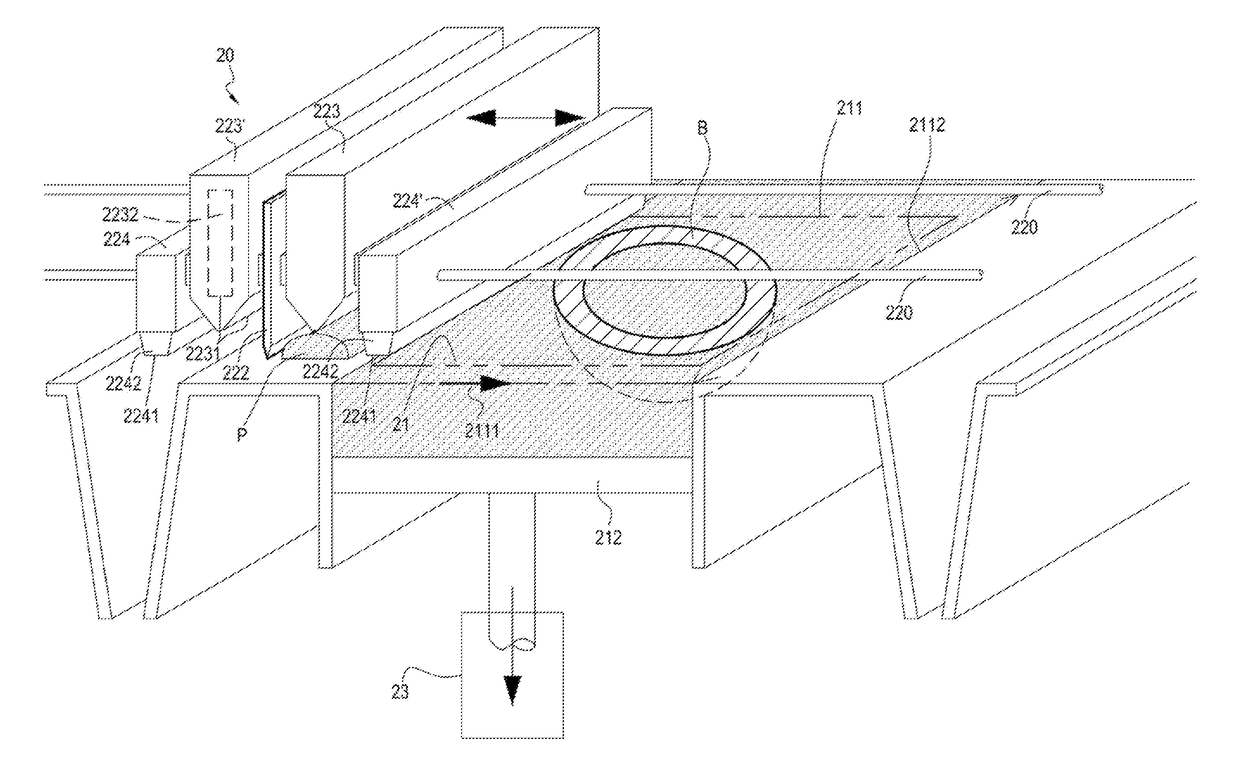
[0022]As shown in FIG. 2 and FIG. 3, a structure of a 3D jet printing apparatus 20 having a reciprocating jetting molding mechanism of this embodiment includes: a molding platform mechanism 21, a jet printing mechanism 22, and a vertical lifting mechanism 23. A molding area plane 211 is provided on an upper surface of the molding platform mechanism 21, where the molding area plane 21...


PUM

PropertyMeasurementUnit
Widthaaaaaaaaaa

Abstract

A 3D jet printing apparatus having a reciprocating jetting molding mechanism includes: a molding platform mechanism, a jet printing mechanism, and a vertical lifting mechanism; where the molding platform mechanism has a molding area plane; the jet printing mechanism is provided above the molding platform, and can correspondingly perform reciprocating movement of forward and reverse strokes; the jet printing mechanism includes a powder spreading unit, powder supply units, and jet printing units; the powder supply units can drop a powder material to the molding area plane; the powder spreading unit then spreads flat the powder material on the molding area plane, and subsequently the jet printing units perform binder jet printing on the powder material that is spread flat; and after the jet printing mechanism performs a stroke once, the vertical lifting mechanism adds a vertical stacking distance between the jet printing mechanism and the molding platform mechanism.

Description

CROSS-REFERENCE TO RELATED APPLICATION[0001]This application claims the benefit of Taiwan Patent Application No. 105113537, filed on Apr. 29, 2016, which is hereby incorporated by reference for all purposes as if fully set forth herein.BACKGROUNDTechnical Field[0002]The present disclosure relates to a three-dimensional (3D) printing apparatus for performing an additive molding method by using powder materials in cooperation with binders, and more specifically, to a fast 3D jet printing apparatus having a reciprocating jetting molding mechanism.Related Art[0003]According to a definition, which is made by American Society for Testing and Materials (ASTM), of “Additive Manufacturing (AM)”, also called “3D printing”, the AM is a process of material process bonding; the technology processes 3D model data by using computer-aided design (CAD) and stacks materials layer by layer to produce 3D objects; the additive process is different from a conventional subtractive manufacturing manner (fo...

Claims


Application Information

Patent Timeline
IPC IPC(8): B33Y30/00
CPCB29C67/0085B33Y30/00B29C67/0081B29C64/165B29C64/236B29C64/336
Inventor KUO, SHIN-HONGWU, CHENG-BOWU, CHING-TSAI
Owner METAL INDS RES & DEV CENT
Why Eureka
Try Eureka